Bumper Structure for an Automatic Moving Device

a technology of automatic moving and bumper structure, which is applied in the direction of adaptive control, computer control, instruments, etc., can solve the problems of high production cost, high cost and structural complexity of robots, and high production cost, and achieve the effect of low production cost and simple structur

Inactive Publication Date: 2010-09-16
WEISTECH TECH CO LTD
View PDF8 Cites 25 Cited by
  • Summary
  • Abstract
  • Description
  • Claims
  • Application Information

AI Technical Summary

Benefits of technology

[0009]An object of the present invention is to provide a bumper structure that allows a moving device to change directions when bumping into an obstacle, with the advantages of low cost of production and being simple structured.

Problems solved by technology

In recent years, intelligent robotic systems have been widely used in factory automations, hospital automations, museum tour guides, surgical auxiliary systems, space explorations, military applications, domestic services, office services, entertainment purposes and even performed dangerous mission for humans.
High cost and structurally complex robots usually utilize different types of sensors simultaneously for accurate obstacle detection and avoid impacts.
However, although visual sensors, ultrasonic sensors and infrared sensors may be effective at spotting and avoiding obstacles, but the disadvantages include the high cost of production and being structurally complicated, also, when the robot moves too fast and the sensors cannot react in time and impacts with the obstacle, the sensors are unable to provide buffer.
Other methods for robots to effectively detect and avoid obstacles include the use of infrared signals or safety magnetic strips for the construction of virtual walls, even though these methods may limit the robots' movements to avoid obstacles, but they are ineffective when it comes to avoiding moving obstacles (such as cats, dogs and humans etc.), and the methods of use are rather inconvenient.
Even though the domestic robots (such as Roomba the vacuum robot and Scooba the ground washing robot developed by iRobot,) sold on the current market usually contain bumpers to lower the damages from impacts, but the bumpers are usually only configured at the front of the robots, therefore when the robot turns around or backs up and impacts with the obstacle with its sides or the back would limit the bumper from providing buffer protection.

Method used


Image

  • Bumper Structure for an Automatic Moving Device
  • Bumper Structure for an Automatic Moving Device
  • Bumper Structure for an Automatic Moving Device

Examples


Embodiment Construction

[0027]Some preferred embodiments of the present invention will now be described in greater detail. However, it should be recognized that the preferred embodiments of the present invention are provided for illustration rather than limiting the present invention. In addition, the present invention can be practiced in a wide range of other embodiments besides those explicitly described, and the scope of the present invention is not expressly limited except as specified in the accompanying claims.

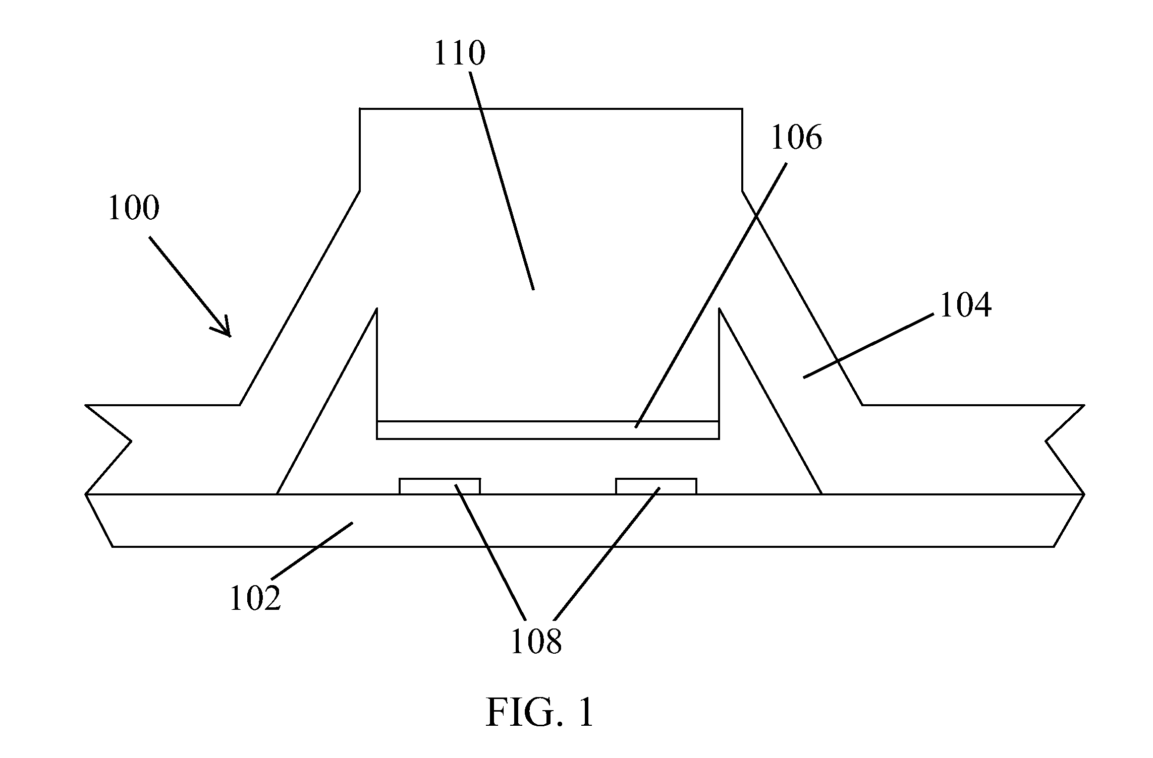
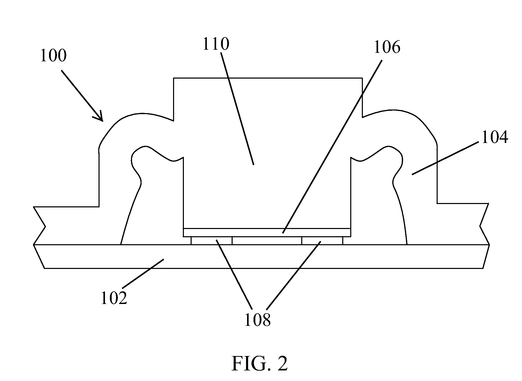
[0028]Refer to FIG. 1, it illustrates the cross section diagram for the preferred embodiment of a bumper structure before impact, according to the present invention. Bumper structure 100 comprises a base 102, an elastic housing 104 and a conductive terminal 106. As shown, a plurality of conductive sheets 108 is formed over base 102; elastic housing 104 is formed over base 102, with a protruding actuator section 110 formed within elastic housing 104, and actuator section 110 is parallel to condu...


PUM


Abstract

The present invention provides a bumper structure for an automatic moving device which directs the moving device to change directions when bumping into an obstacle. The bumper structure of the present invention comprises a base, an elastic housing and a conductive terminal. A plurality of conductive sheets is formed over the base, wherein the conductive sheets are coupled to the control circuit of a moving device via the base. The elastic housing is formed over the base, with a protruding actuator section formed within the elastic housing, and the actuator section is parallel to the conductive sheets. The conductive terminal is formed at the bottom of the actuator section but is not in contact with the conductive sheets. The elastic housing may provide buffer when bumping into an obstacle, and the force generated by the impact presses the actuator section downwards, allowing conductive terminal of the actuator section to couple with the plurality of conductive sheets, thereby connects the plurality of conductive sheets and sends a signal to the control circuit of the moving device, directing the moving device to change directions.

Description

TECHNICAL FIELD[0001]The present invention relates to bumper structures, especially to a bumper structure which directs a moving device to change directions when bumping into an obstacle.BACKGROUND[0002]With the continuous development and improvement in technology, scenes in the movies where robots serving humans and the coexistence of humans and robots is now a dream that may be realized. In recent years, intelligent robotic systems have been widely used in factory automations, hospital automations, museum tour guides, surgical auxiliary systems, space explorations, military applications, domestic services, office services, entertainment purposes and even performed dangerous mission for humans.[0003]As robots are now viewed as the emerging industry for next generation, many organizations have invested a large amount of resources into the research and development of robots, which allowed robots for various purposes to be present to the public continually, such as the robotic pets fo...

Claims


Application Information

Patent Timeline
Patent Type & Authority Applications(United States)
IPC IPC(8): G05B15/02
CPCA47L2201/04B60R19/483B25J19/0091B25J13/081
Inventor HSU, WEI
Owner WEISTECH TECH CO LTD
Why Eureka
Try Eureka