Flexible Wrap of Rotatably Interlocking Fluted Strips

a flexible wrap and fluted strip technology, applied in the direction of covering/lining, building components, balusters, etc., to achieve the effect of facilitating the wrapping of the resulting flexible wrap around an object and similar cross-sectional shap

Active Publication Date: 2010-09-23
MACKENZIE DOUGLAS A
View PDF21 Cites 23 Cited by
  • Summary
  • Abstract
  • Description
  • Claims
  • Application Information

AI Technical Summary

Benefits of technology

[0008]As a result, the socket cross-section of the interlocking fluted strip may be configured to rotatably interlock with a second ball cross-section of a second interlocking fluted strip, and the ball cross-section of the interlocking fluted strip may be configured to rotatably interlock with a third socket cross-section of a third interlocking fluted strip. The interlocking fluted strip may be rotatably interlocked with the second interlocking fluted strip along the first longitudinal length of the first end of the strip and also rotatably interlocked with the third interlocking fluted strip along the second longitudinal length of the second end of the strip such that wrapping the resulting flexible wrap around an object is facilitated.
[0009]In another embodiment, a flexible wrap of rotatably interlocking fluted strips is provided. The flexible wrap may include a set of interlocking fluted strips, each interlocking fluted strip within the set may have a substantially similar cross-sectional shape. The set of interlocking fluted strips may include a first interlocking fluted strip, a second interlocking fluted strip, and a third interlocking fluted strip. The first interlocking fluted strip may include a socket means for rotatably interconnecting the first interlocking fluted strip with the second interlocking fluted strip along a first longitudinal length of the first interlocking fluted strip such that the first interlocking fluted strip rotates with respect to the second interlocking fluted strip along the first longitudinal length. The first interlocking fluted strip may also include a ball means for rotatably interconnecting the first interlocking fluted strip with the third interlocking fluted strip along a second longitudinal length of the first interlocking fluted strip such that the first interlocking fluted strip rotates with respect to the third interlocking fluted ...

Problems solved by technology

With respect to U.S. Pat. No. 5,956,920, the Background of the '220 patent states “multiple piece assemblies, however, require significant assemblage efforts and include several connec...

Method used


Image

  • Flexible Wrap of Rotatably Interlocking Fluted Strips
  • Flexible Wrap of Rotatably Interlocking Fluted Strips
  • Flexible Wrap of Rotatably Interlocking Fluted Strips

Examples


Embodiment Construction

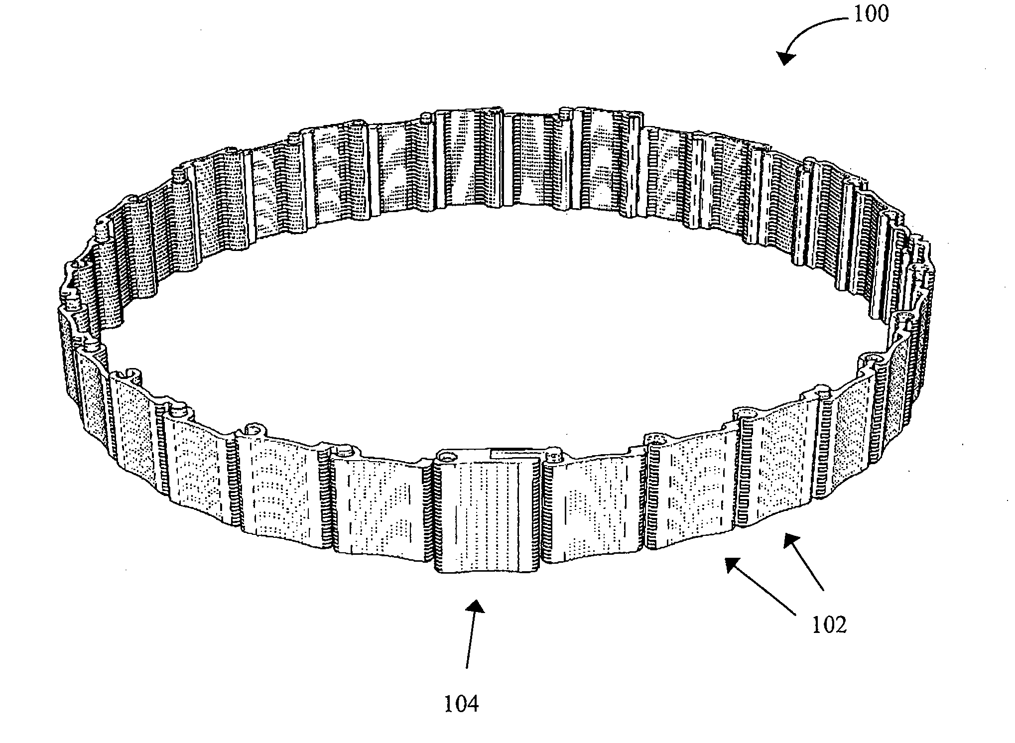
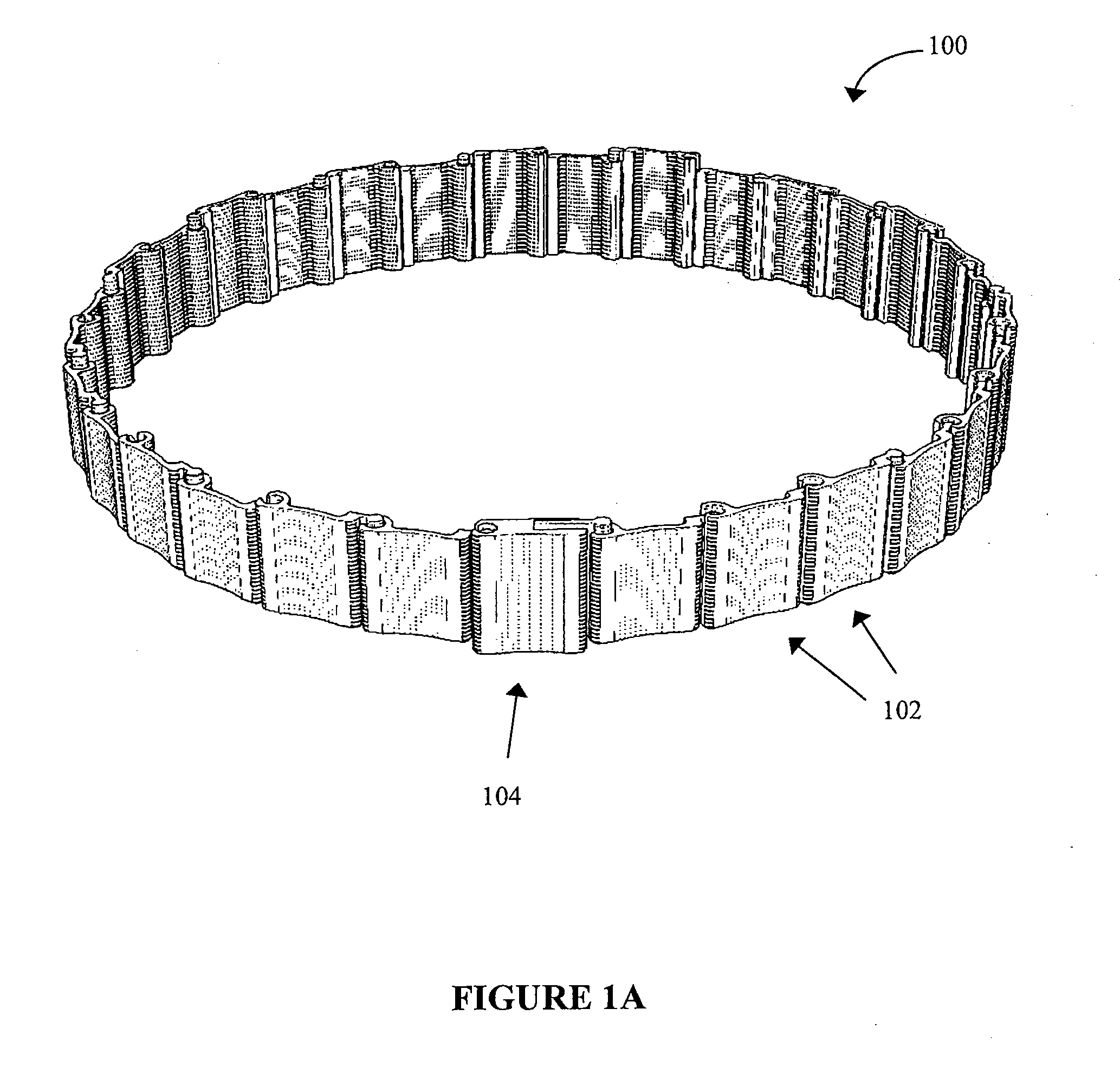
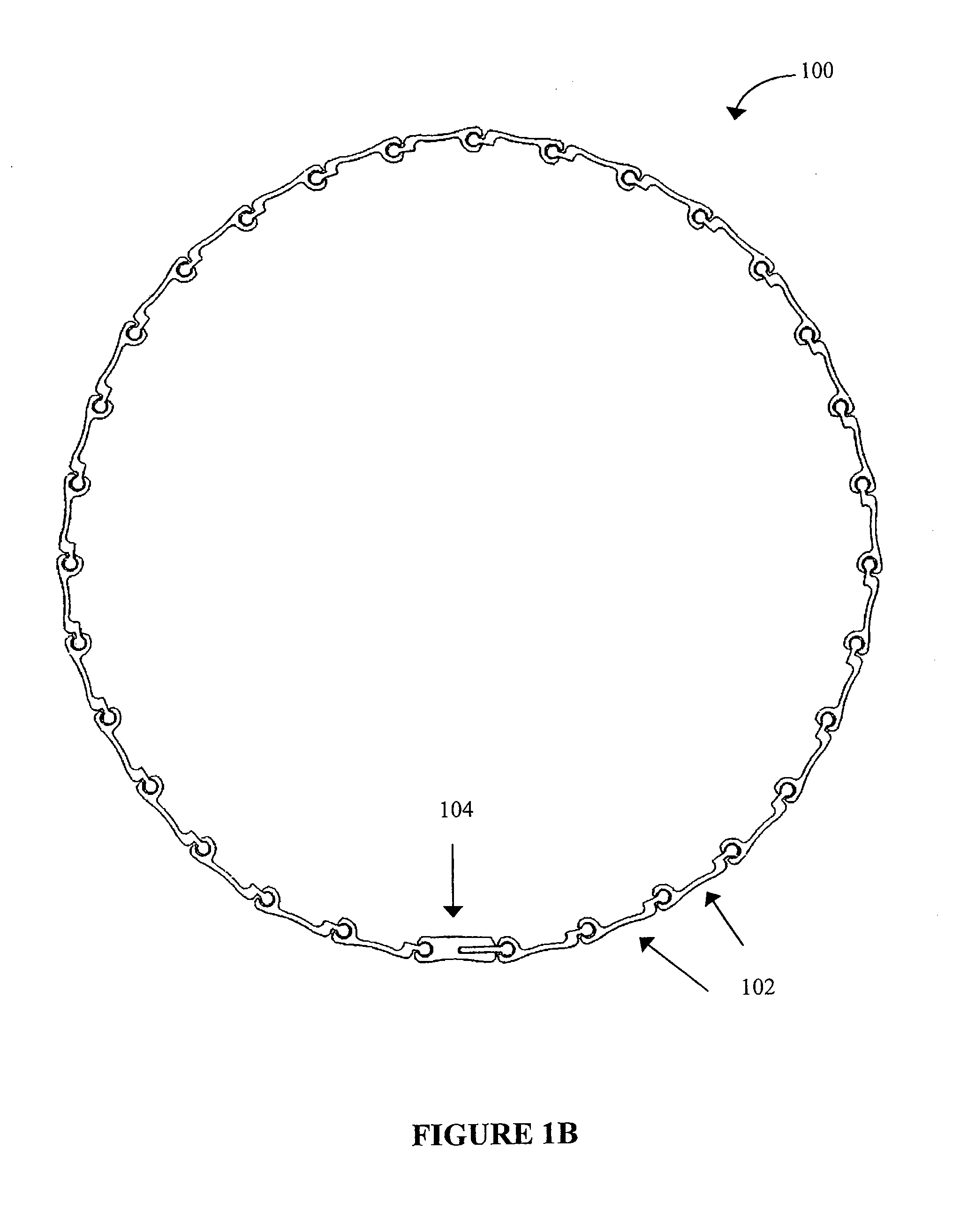
[0024]A flexible wrap of rotatably interconnected fluted strips is provided. Each interlocking fluted strip may be rotatably interlocked with adjacent interlocking fluted strips to form the flexible wrap. Each interlocking fluted strip may have cross-sectional areas having a substantially similar shape(s) and / or size, such as similarly shaped socket cross-sections and ball cross-sections discussed herein.

[0025]Each interlocking fluted strip may include a cross-sectional area having a socket means on one end and a ball means on the other end. The socket means may lockingly accept a ball means of an adjacent fluted strip. The ball means may be lockingly accepted by a socket means of a second adjacent strip. The socket means and ball means may also be configured to allow two adjacent, interlocked fluted strips to longitudinally rotate with respect to one another after being interconnected.

[0026]In one aspect, the socket means of a first fluted strip may include a cross-section having a...


PUM


Abstract

A flexible wrap of rotatably interlocking fluted strips is provided. The fluted strips may have similarly shaped cross-sectional areas and be rotatably interconnected with one another such that the flexible wrap may be wrapped around an object. One end of a fluted strip may have a socket means for rotatably interlocking with an adjacent fluted strip. The socket means may have a circular inner diameter and two curved arms with an opening between their ends. The opposite end of the fluted strip may have a ball means for rotatably interlocking with another adjacent fluted strip. The ball means may have a circular outer diameter sized to slide into the circular inner diameter of the socket means of an adjacent fluted strip, and an arm sized to slide between the opening of the curved arms, during assembly. One fluted strip may be designed to join in the middle to facilitate wrapping.

Description

RELATED APPLICATIONS[0001]The present Application claims priority to U.S. Provisional Application Ser. No. 61 / 202,640, filed on Mar. 19, 2009 and entitled Utility Pole to Lamp Post Conversion Kit, the entirety of which is hereby incorporated by reference. The present Application is also related to U.S. Design Patent Ser. No. ______, filed on the same day as the present Application, and which is also incorporated herein by reference in its entirety.FIELD[0002]The present invention generally relates to column wrap assemblies. More particularly, a multi-piece column wrap assembly for upgrading pillars and other objects is provided.BACKGROUND[0003]Conventional column wraps may be used to cover a support or structural column of a house. Recent column wraps include the column wrap kits manufactured by AIC Millworks. These column wraps may be manufactured from PVC and include two pieces that snap together. The two pieces may each include two flat sides affixed at a right angle forming a L-...

Claims


Application Information

Patent Timeline
IPC IPC(8): E04F13/073E04C3/30
CPCE04C3/30E04F19/00E04F11/1842
Inventor MACKENZIE, DOUGLAS A.
Owner MACKENZIE DOUGLAS A
Why Eureka
Try Eureka