Drive for a Hydraulic Excavator

a technology for hydraulic excavators and excavators, which is applied in the direction of couplings, belts/chains/gearings, and gear control. it can solve the problems of simply destroying energy and destroying a considerable amount of energy

Inactive Publication Date: 2010-09-23
LIEBHERR FRANCE
View PDF26 Cites 51 Cited by
  • Summary
  • Abstract
  • Description
  • Claims
  • Application Information

AI Technical Summary

Benefits of technology

[0008]In principle, it is known already that a slewing gear of an excavator is operated in a closed circuit. In known hydraulic excavators, however, the one reversible adjusting unit is an adjustable hydraulic pump, whereas the associated hydraulic motor is rigid, so that the high-pressure side and the low-pressure side alternate with the direction of rotation of the uppercarriage.
[0009]In accordance with the present invention, on the other hand, in which the hydraulic units both are hydraulic, reversible adjusting units, both elements are operable both as pump and as motor. Thus, as far as the reversible adjusting units here constitute hydraulic components, one side of the closed circuit between the two reversible adjusting means and a first accumulator can be under high pressure, whereas the other side of the closed circuit always is under low pressure, in contrast to the aforementioned prior art.
[0010]Upon actuation of the slewing gear, braking energy is passed on for storage from the one adjusting unit for the case of slowing down the uppercarriage of the excavator. If necessary, this energy can also be passed on via the second reversible adjusting unit to further units, such as pumps, which can be coupled with the second adjusting unit.
[0011]In the accumulator, the braking energy of the uppercarriage now is stored, in order to be used again during the next acceleration. This energy then is supplied to the reversible adjusting unit serving as slewing gear motor. If necessary, however, the energy stored in the accumulator can also be supplied to the other reversible adjusting unit, by means of which for example the working hydraulics of further connected systems such as the hoisting gear etc. is supported.
[0006]In accordance with the invention, this object is solved by the combination of the features herein.
[0013]Thus, at least one of the reversible adjusting units can be connectable with the drive unit of the excavator, for example the Diesel engine. Since the charging and discharging operations have a certain efficiency, the energy accumulator can correspondingly be recharged via this drive unit.
[0014]The reversible adjusting units advantageously are hydraulic adjusting units, which can reverse the flow direction with the same sense of rotation, so that they can operate as motor or pump. The at least one accumulator advantageously is a hydraulic accumulator.
[0020]Preferably, one of the hydraulic adjusting units can also be connected with a hydraulic accumulator.

Problems solved by technology

In known systems, the energy released simply is destroyed during the lowering movement of the hoisting equipment.
Since the weight of the equipment represents a multiple of the charge in the bucket, a considerable amount of energy is destroyed here.

Method used


Image

  • Drive for a Hydraulic Excavator
  • Drive for a Hydraulic Excavator
  • Drive for a Hydraulic Excavator

Examples


Embodiment Construction

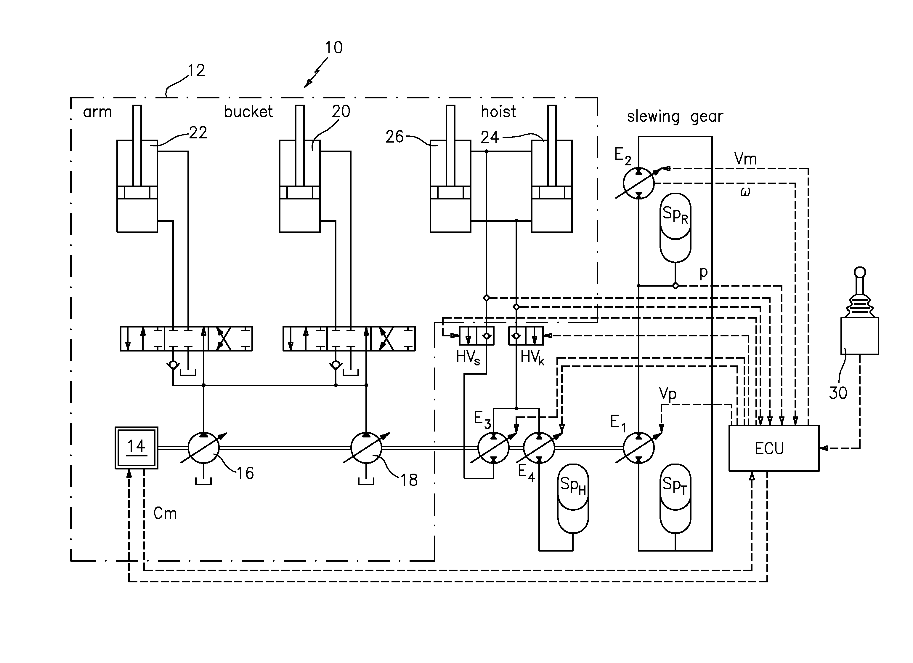
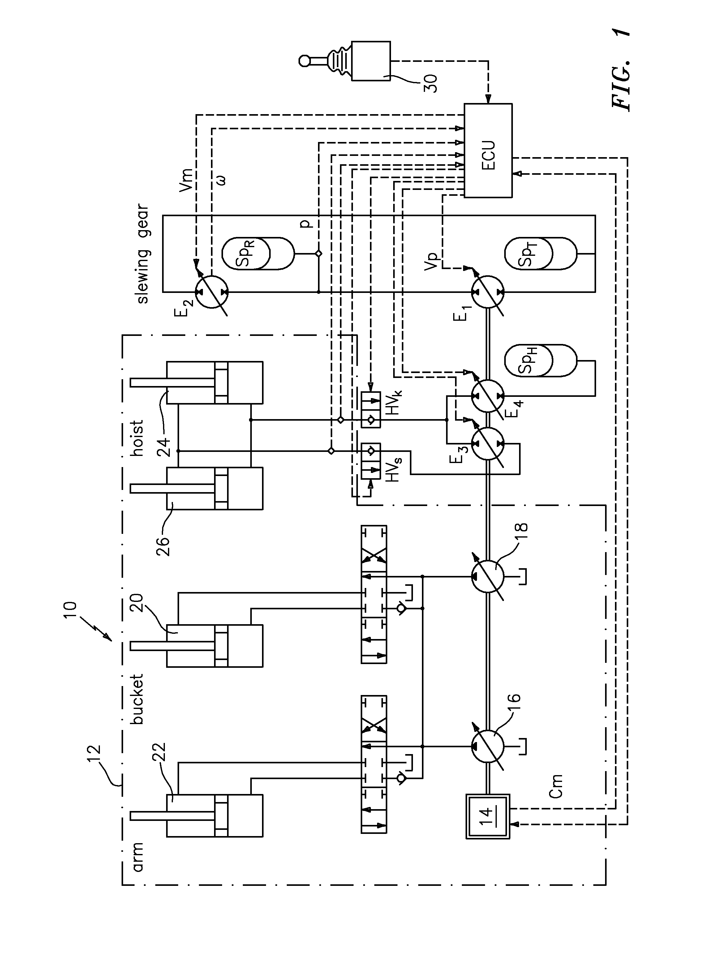
[0025]In FIG. 1, the circuit diagram of a drive of the invention is shown, in which a number of individual drives are driven hydraulically. The individual drives on the one hand include the drive for a dipper arm, for a bucket, for the hoisting cylinder and for the stewing gear. Within the dash-dotted line 12, the individual components of a known hydraulic drive for a hydraulic excavator (not shown here in detail) are represented. First of all, a schematically represented drive unit 14 is provided here, which usually is a Diesel engine. Via the Diesel engine, hydraulic pumps 16 and 18 are driven, which supply corresponding double-acting hydraulic cylinders 20 and 22 with hydraulic oil. The double-acting hydraulic cylinder 20 is the drive cylinder for the non-illustrated bucket of the excavator. The double-acting hydraulic cylinder 22 is the drive cylinder for the likewise non-illustrated dipper arm. Beside the double-acting hydraulic cylinders 20 and 22, two double-acting hydraulic ...


PUM


Abstract

The present invention relates to a drive for an excavator with a number of individual drives, such as a slewing gear drive, a hoist drive, a bucket drive and an arm drive, wherein for the slewing gear drive two reversible adjusting units are provided, which are at least coupled with an energy accumulator.

Description

BACKGROUND OF THE INVENTION[0001]This invention relates to a drive for a construction machine, in particular for an excavator with a number of individual drives, such as at least one rotatory drive, e.g. a slewing gear drive, and at least one linear drive, e.g. a hoist drive, a bucket drive and / or an arm drive.[0002]From DE 103 43 016 A1 it is known already to actuate a double-acting hydraulic cylinder by means of two hydraulic pumps. One of the two hydraulic pumps is connected with the two working chambers of the double-acting hydraulic cylinder in a closed circuit. The second hydraulic pump, on the other hand, only is connected with the piston-side working chamber in an open circuit. The two hydraulic pumps each have a variable displacement. By adjusting a corresponding displacement ratio over the different volume flow in the piston-side working chamber, the working chamber on the piston rod side is taken into account.[0003]From DE 10 2007 025 742 A1, a hydrostatic drive with a fi...

Claims


Application Information

Patent Timeline
Patent Type & Authority Applications(United States)
IPC IPC(8): F15B1/027
CPCE02F9/123E02F9/2217F15B2211/20523F15B2211/20569F15B2211/20576F15B2211/212F16H61/4096F15B2211/6313F15B2211/6336F15B2211/6346F15B2211/6658F15B2211/88F15B2211/6309
Inventor BOEHM, DANIELLANDMANN, THOMASSPATH, RALF
Owner LIEBHERR FRANCE
Why Eureka
Try Eureka