Method and apparatus for delivery of a fuel and combustion air mixture to a gas turbine engine

a gas turbine engine and combustion air technology, applied in the direction of engine ignition, lighting and heating apparatus, engine/propulsion engine, etc., can solve the problems of reducing the emissions performance of the gas turbine engine, overheating/or the combustor premixing section, etc., to achieve the effect of reducing the emissions of co and hc, and reducing the emissions of the engin

Active Publication Date: 2010-09-23
GENERAL ELECTRIC CO
View PDF13 Cites 46 Cited by
  • Summary
  • Abstract
  • Description
  • Claims
  • Application Information

AI Technical Summary

Problems solved by technology

Operational issues involved with combustors operating with lean pre-mixing of fuel and air involve the presence of combustible mixtures within the pre-mixing sections of the combustor, upstream of the combustor reaction zone.
Results of combustion occurring within the premixing zone of the combustor may include degradation of emissions performance of the gas turbine engine and / or overheating of the combustor premixing section and lower than desirable durability.
Alternatively, regions in the air / fuel flow field where the concentration of fuel versus air is leaner than in other regions may lead to quenching, with a failure to oxidize hydrocarbons and or carbon monoxide, leading to higher than desired CO and HC emissions levels.

Method used


Image

  • Method and apparatus for delivery of a fuel and combustion air mixture to a gas turbine engine
  • Method and apparatus for delivery of a fuel and combustion air mixture to a gas turbine engine
  • Method and apparatus for delivery of a fuel and combustion air mixture to a gas turbine engine

Examples


Embodiment Construction

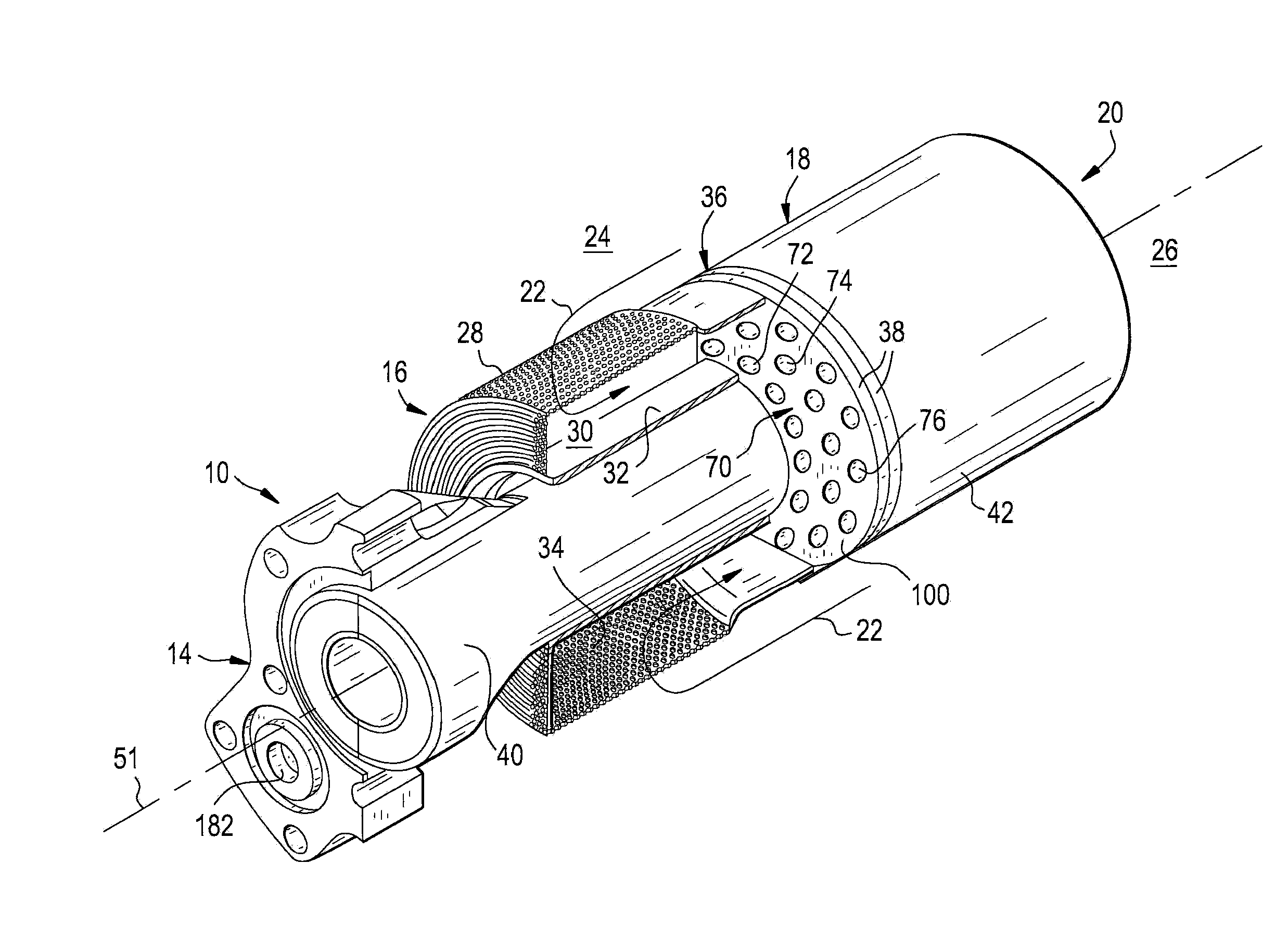
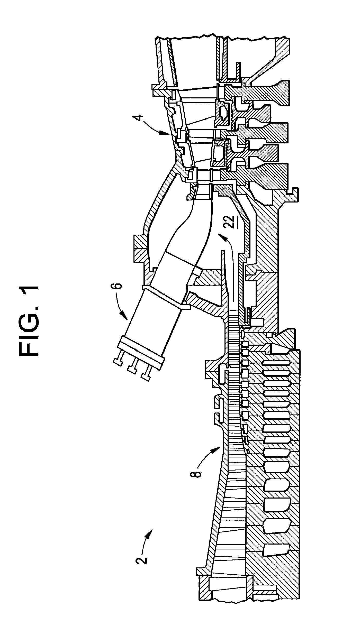
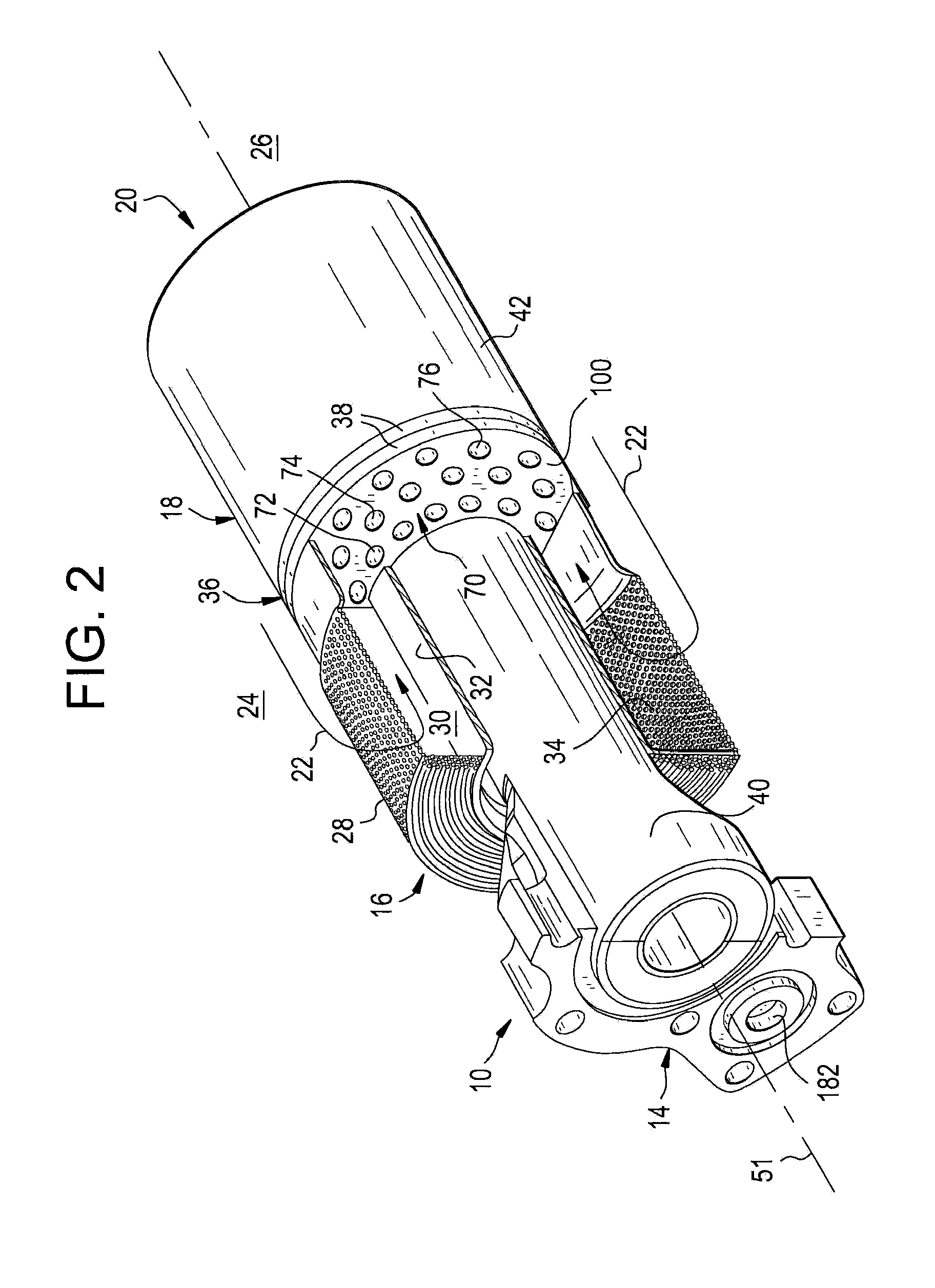
[0019]In one, non-limiting embodiment of the invention shown in FIGS. 1 and 2, a gas turbine engine 2 comprises a turbine 4, a combustor 6 and a compressor 8 for delivery of compressed combustion air 22 to the combustor. The combustor 6 combusts fuel with the combustion air to deliver hot combustion gas through an outlet to the turbine 4.

[0020]A burner assembly 10 for installation in to the combustor 6 of a gas turbine engine 2 is shown. The burner assembly 10 comprises four primary sections, by function, including a fuel inlet and distribution manifold assembly 14, an air inlet and flow conditioner assembly 16, a fuel nozzle assembly 18 and an outlet zone 20. Combustion air 22 enters the burner assembly from a high-pressure plenum 24 surrounding the entire assembly, with the exception of the outlet zone 20 that is disposed within the combustor reaction zone 26 of the combustor 6. The combustion air 22 for the burner assembly 10 enters the air inlet and flow conditioner assembly 16 ...


PUM


Abstract

A nozzle has combustion air passages extending from a first, upstream end to a second, downstream end. A fuel distribution manifold is associated with the first, upstream end of the nozzle. Combustion air passages correspond to, and align with the air passages in the nozzle. Fuel distribution grooves are formed in one end of the fuel distribution manifold disk and extend from a central opening to the air passages. A fuel circuit cover closes the fuel distribution grooves to define fuel passages that extend from the central opening to the combustion air passages. A fuel supply conduit communicates with the central opening and the fuel passages for delivery of fuel to the combustion air in the air passages.

Description

BACKGROUND OF THE INVENTION[0001]The subject matter disclosed herein relates to combustion systems for gas turbine engines. Manufacturers and operators of gas turbine engines desire to produce and operate gas turbines that will operate at high efficiency while producing reduced quantities of governmentally regulated combustion constituents. The primary regulated exhaust gas constituents produced by gas turbine engines burning conventional hydrocarbon fuels are oxides of nitrogen (“NOx”), carbon monoxide (“CO”) and unburned hydrocarbons (“HC”). The oxidation of nitrogen in internal combustion engines is dependant upon the maximum hot gas temperature in the combustion system reaction zone. The rate of chemical reactions forming oxides of nitrogen is a function of temperature. Controlling the temperature of combustion in the combustion chamber to a desired temperature will assist in controlling the formation of NOx components.[0002]One method of controlling the temperature of the combu...

Claims


Application Information

Patent Timeline
Patent Type & Authority Applications(United States)
IPC IPC(8): F02C7/22
CPCF23R3/286F23R3/12
Inventor DAVIS, JR., LEWIS BERKLEYJOHNSON, THOMAS EDWARDSTEWART, JASON THURMAN
Owner GENERAL ELECTRIC CO
Why Eureka
Try Eureka