Construction machine

a construction machine and belt technology, applied in soil-shifting machines/dredgers, vehicular safety arrangments, transportation and packaging, etc., can solve the problem that the service worker who has climbed onto the crawler belt cannot grab the louver like a handrail, and achieve the effect of less spatial loss

Active Publication Date: 2010-09-23
NIHON KENKI CO LTD
View PDF2 Cites 29 Cited by
  • Summary
  • Abstract
  • Description
  • Claims
  • Application Information

AI Technical Summary

Benefits of technology

[0019]Consequently, the narrow space of the equipment room, which is provided beneath the connecting support member, can be effectively utilized with less spatial losses for accommodation of various onboard equipments including an air cleaner.

Problems solved by technology

In this case, however, a servicing worker who has climbed onto a crawler belt cannot grab the louver like a hand-rail for the purpose of stabilizing his or her posture while performing a cleaning job on the crawler belt.

Method used


Image

  • Construction machine
  • Construction machine
  • Construction machine

Examples


Embodiment Construction

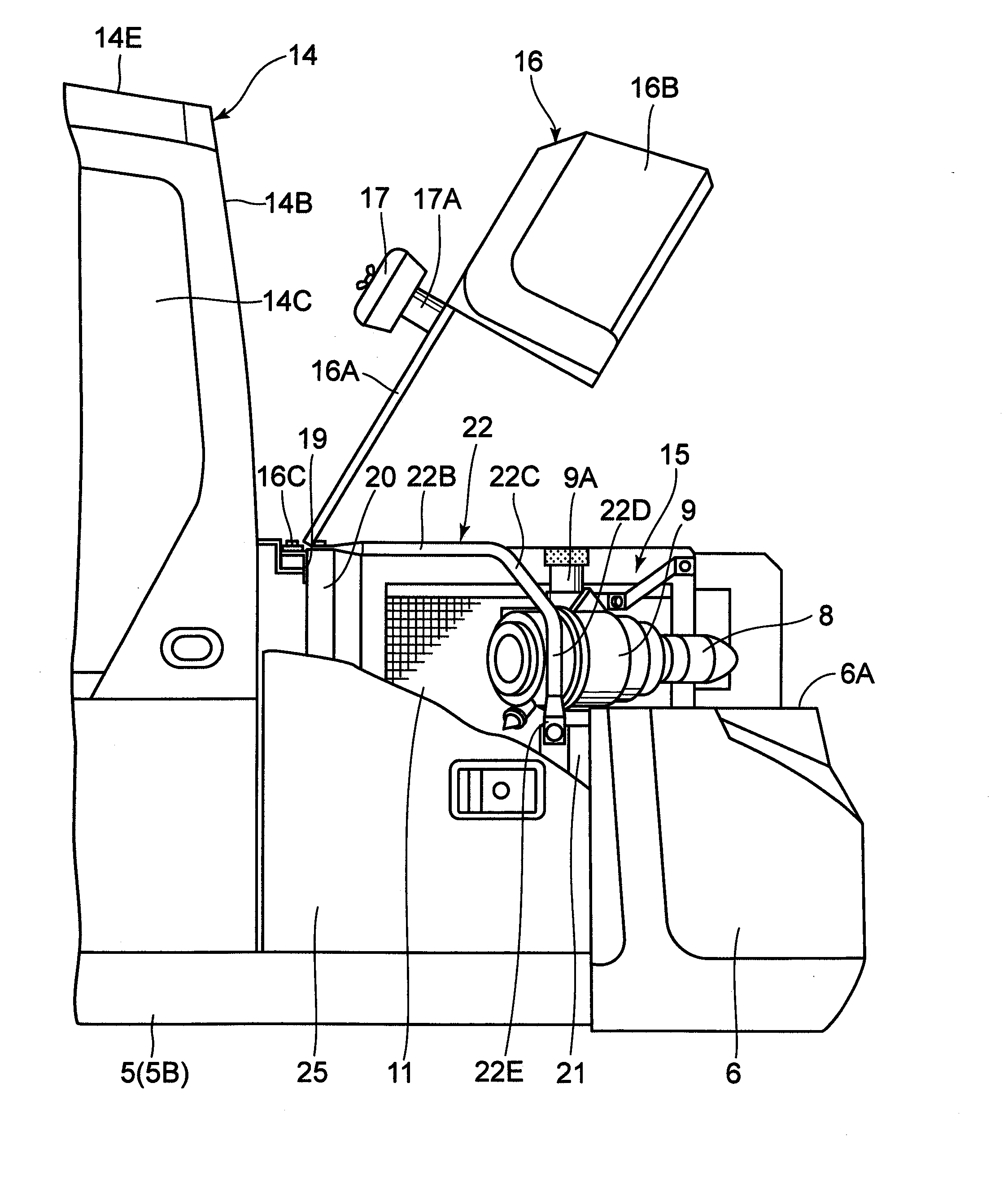
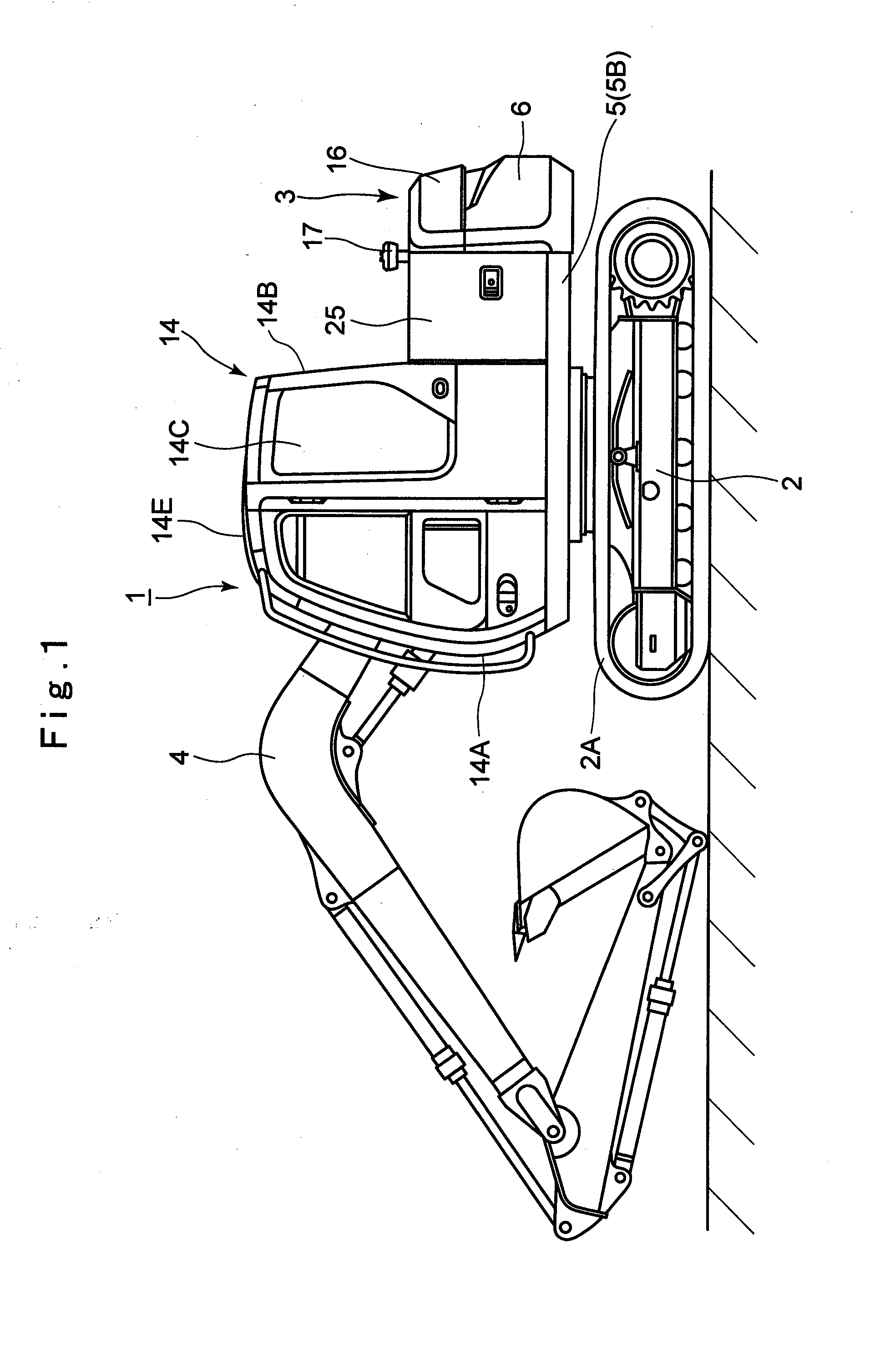
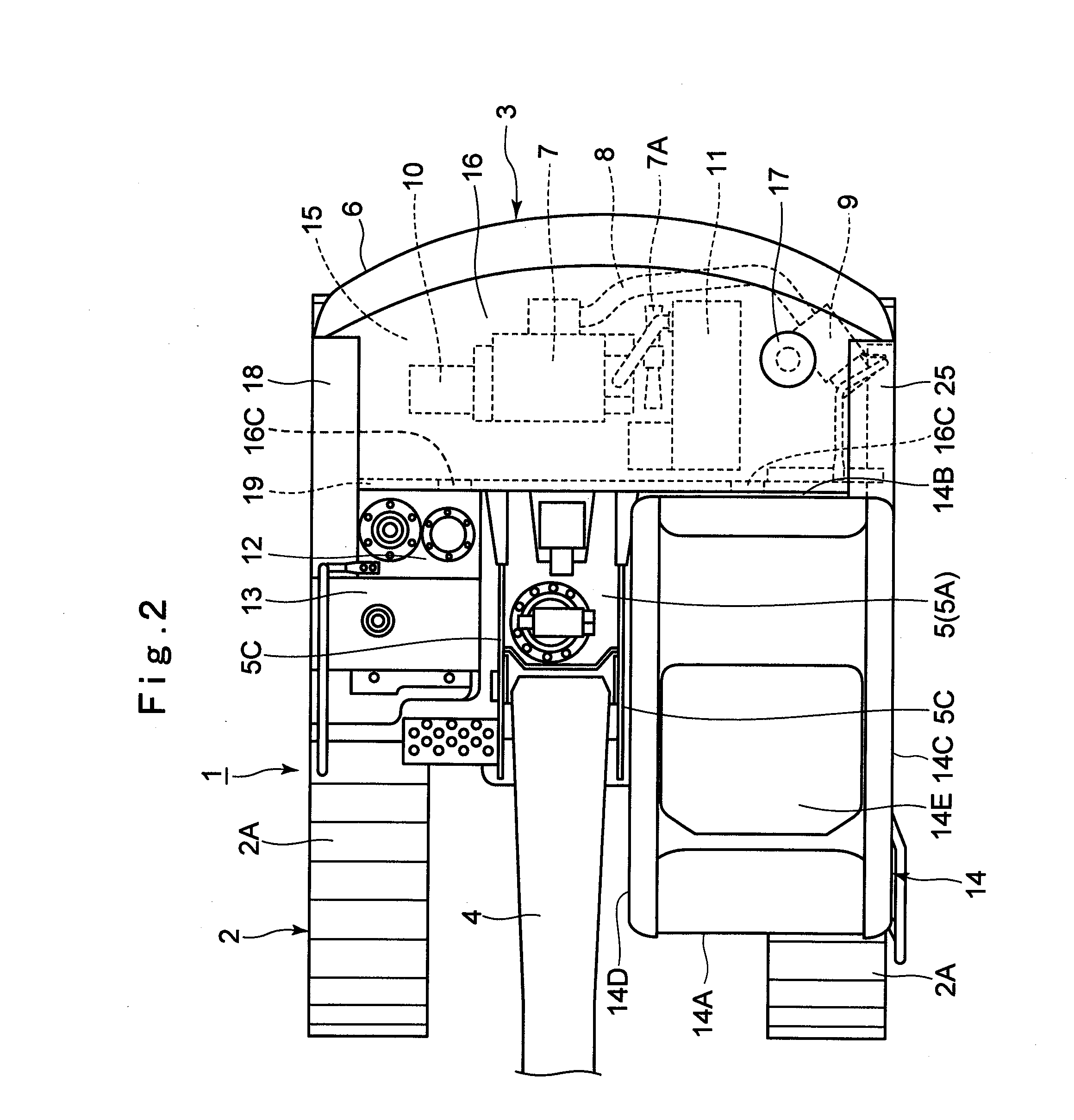
[0036]Hereafter, with reference to FIGS. 1 through 15, the present invention is described more particularly by way of its preferred embodiments which are applied by way of example to a hydraulic excavator.

[0037]In the drawings, indicated at 1 is a hydraulic excavator as a typical example of construction machines. The hydraulic excavator 1 is built as a small size hydraulic excavator which is, for example, smaller than 7 tons in gross weight, and largely constituted by an automotive lower structure 2 with right and left crawler belts 2A, an upper revolving structure 3 rotatably mounted on the lower structure 2, and a working mechanism 4 liftably mounted on a front portion of the upper revolving structure 3. The upper revolving structure 3 is largely constituted by a revolving frame 5, a counterweight 6, a cab 14 and a machine room 15, which will be described hereinafter.

[0038]Indicated at 5 is a revolving frame which constitutes a base of the upper revolving structure 3. As shown in ...


PUM


Abstract

A machine room (15) is provided between a cab (14) and a counterweight (6) which are mounted on a revolving frame (5) to accommodate an engine (7). The machine room (15) is built of a left front support member (20), a rear support member (21), a connecting support member (22) and a left side housing door (25). A horizontal grip portion (22B) and an inclined grip portion (22C) are provided in intermediate portions of the connecting support member (22) which connects the left front support member (20) and the rear support member (21). By opening the left side housing door (25), the inclined grip portion (22C) of the connecting support member (22) comes out, permitting a servicing worker to hold on thereto helping him or her perform a cleaning job of a rear face portion (14B) of a cab (14) in an efficient manner.

Description

TECHNICAL FIELD[0001]This invention relates to a construction machine like a hydraulic excavator, wheel loader or the like.BACKGROUND ART[0002]Generally, a hydraulic excavator, for example, is largely constituted by an automotive lower structure, an upper revolving structure rotatably mounted on the lower structure, and a working mechanism built on the front side of the upper revolving structure to be lifted up and down in relation with swing motions of the upper revolving structure, for example, for a ground excavating operation.[0003]In the case of an excavator as mentioned above, the upper revolving structure is including a revolving frame which is in the form of a strong support structure, and a base end portion of the working mechanism is attached to the front side of the revolving frame. A counterweight is attached to the rear side of the revolving frame as a weight balance relative to the working mechanism. Further, an engine and a heat exchanger are mounted on the revolving ...

Claims


Application Information

Patent Timeline
Patent Type & Authority Applications(United States)
IPC IPC(8): B62D25/24E02F9/00
CPCB62D25/10E02F9/0833E02F9/18E02F9/0891E02F9/0866E02F9/00B62D25/08B62D25/24
Inventor MATSUSHITA, MAKOTOTAKEI, TAKESHIISAKA, WATARUWATANABE, KATSUTOSHI
Owner NIHON KENKI CO LTD
Why Eureka
Try Eureka