Hydraulic shock absorber

a technology of shock absorber and shock absorber, which is applied in the direction of shock absorber, axle suspension, liquid based damper, etc., can solve the problems of increasing the cost and not considering the complete closure of the bypass passage, and achieve the effect of large damping for

Inactive Publication Date: 2010-09-23
HONDA MOTOR CO LTD
View PDF8 Cites 17 Cited by
  • Summary
  • Abstract
  • Description
  • Claims
  • Application Information

AI Technical Summary

Benefits of technology

[0006]It is accordingly an object of the present invention to provide a hydraulic sho

Problems solved by technology

However, a push rod is used to reduce the sectional area of the bypass passage, causing a co

Method used


Image

  • Hydraulic shock absorber
  • Hydraulic shock absorber
  • Hydraulic shock absorber

Examples


Embodiment Construction

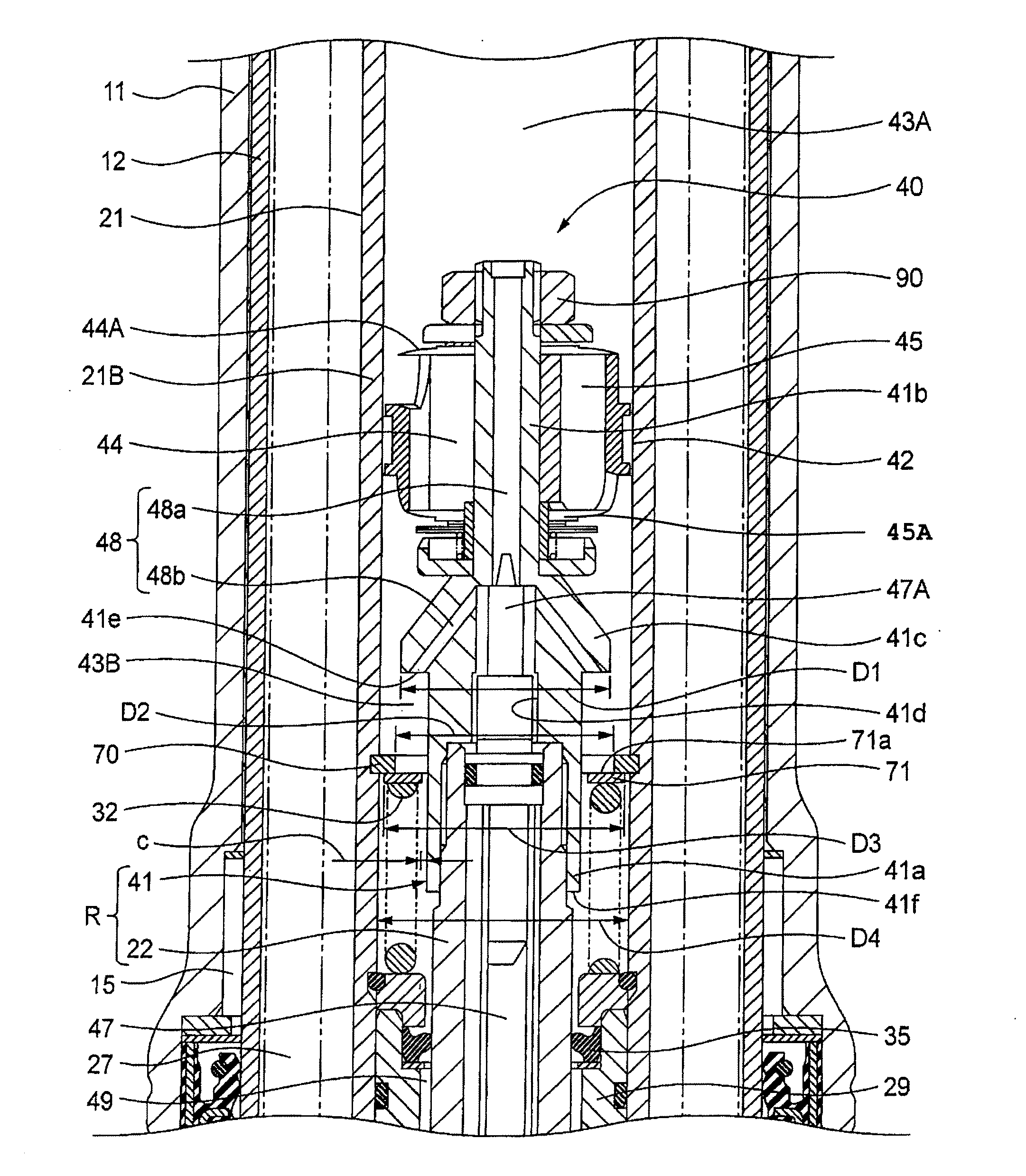
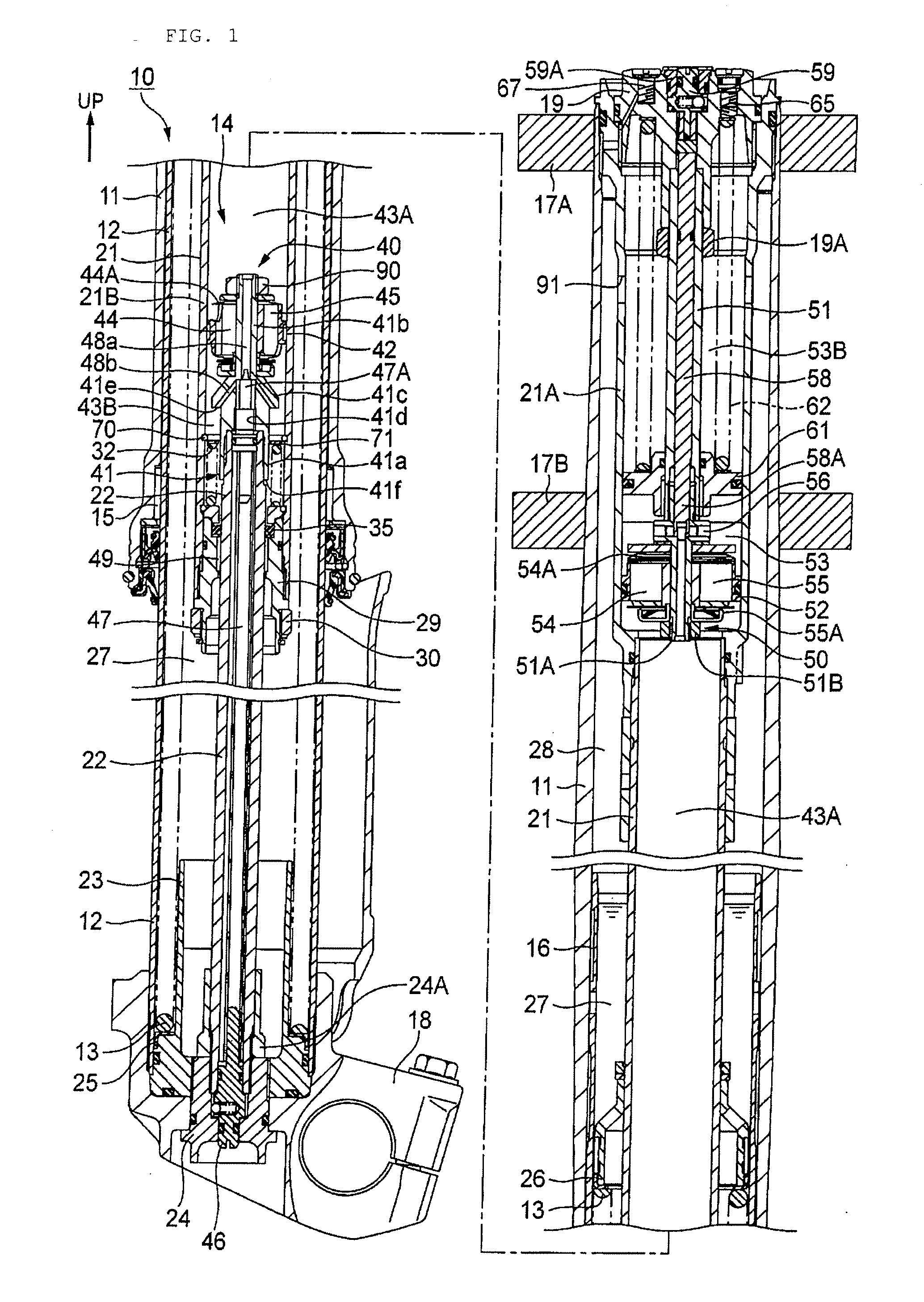
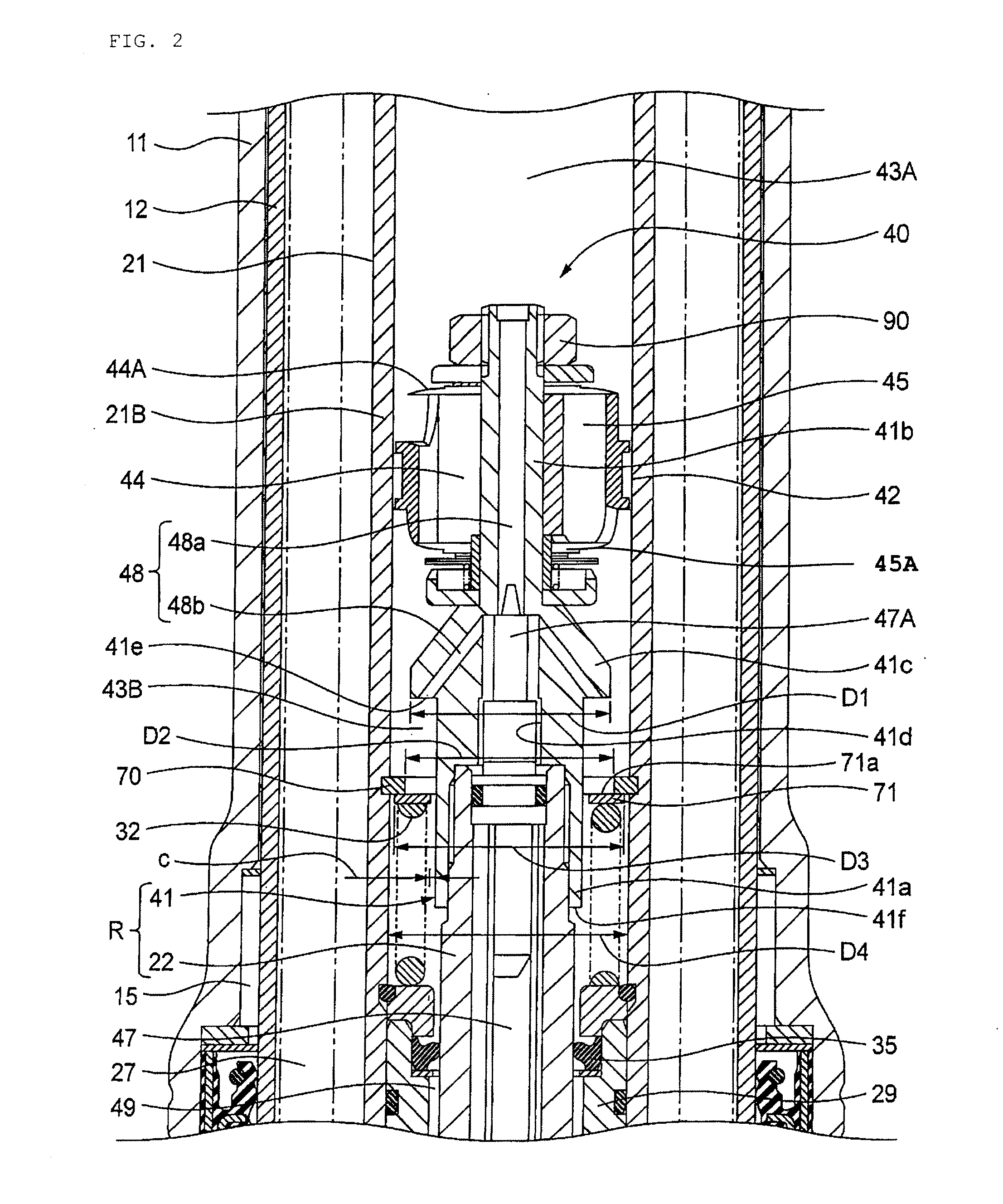
[0028]Some embodiments of the present invention will now be described with reference to FIGS. 1 to 7.

[0029]Referring to FIG. 1, there is shown a front fork as a hydraulic shock absorber according to an embodiment of the present invention. The front fork 10 includes a body-side tube (outer tube) 11, a wheel-side tube (inner tube) 12 slidably inserted in the body-side tube 11, a suspension spring 13 interposed between the two tubes 11 and 12, and a multi-tube type damper 14 provided in the two tubes 11 and 12 in an inverted condition.

[0030]According to one embodiment, a bushing 15 is fitted to the inner circumference of the body-side tube 11 at its lower end portion. The outer circumference of the wheel-side tube 12 is in sliding contact with the bushing 15. A bushing 16 is fitted to the outer circumference of the wheel-side tube 12 at its upper end portion. The inner circumference of the body-side tube 11 is in sliding contact with the bushing 16.

[0031]The body-side tube 11 can be su...


PUM


Abstract

In a hydraulic shock absorber 10, a piston holder 41 has an axial side surface 41e formed with an opening of an inclined hole 48b exposed to a rod-side oil chamber 43B. A block ring 71 capable of closing the opening of the inclined hole 48b is provided around a piston rod body 22 at a position between the axial side surface 41e of the piston holder 41 and the upper end of a rebound spring 32.

Description

BACKGROUND[0001]1. Field[0002]Embodiments of the present invention relate to a hydraulic shock absorber interposed between a vehicle body and a wheel for absorbing shock from a road surface.[0003]2. Description of the Related Art[0004]A conventional hydraulic shock absorber includes a cylinder, a piston rod having a slidable piston inserted in the cylinder, an oil passage formed in the piston so as to make the communication of oil chamber defined on both sides of the piston, and a bypass passage formed in the piston rod so as to make the communication of the oil chambers. Further, in order to reduce a change in attitude of a vehicle body in the case of maximum expansion of the hydraulic shock absorber, the sectional area of the bypass passage is reduced by using an open / close rod to thereby increase a damping force (see Japanese Patent No. 3887107, for example).[0005]In the hydraulic shock absorber described in Japanese Patent No. 3887107, a damping force can be increased in the cas...

Claims


Application Information

Patent Timeline
IPC IPC(8): F16F9/34F16F9/14
CPCB62K25/08F16F9/516B62K2025/048
Inventor UCHIYAMA, MIKIO
Owner HONDA MOTOR CO LTD
Why Eureka
Try Eureka