Evaluation device for evaluating measuring signals, measuring device and method for receiving and evaluating measuring signals

a measuring signal and evaluation device technology, applied in the direction of optical radiation measurement, instruments, digital computer details, etc., can solve the problems of overlaid offset voltage, overlaid offset voltage is correspondingly amplified, and the effect of large amplification of useful signals

Inactive Publication Date: 2010-09-23
ROBERT BOSCH GMBH
View PDF2 Cites 0 Cited by
  • Summary
  • Abstract
  • Description
  • Claims
  • Application Information

AI Technical Summary

Benefits of technology

[0013]In this connection, the present invention has a few advantages. The parasitic offset voltage may be compensated for directly in the analog range, so that subsequently a large amplification of the useful signal is possible at low operating voltages and without adjusting the evaluation circuit. For this, the amplification and the filtering may be adjusted respectively. By currently ascertaining the offset voltage according to the present invention, a more accurate result may be achieved than, for instance, by making a subsequent subtraction of a value that was once ascertained ahead of time. A measuring result that is qualitatively good may thus be obtained.

Problems solved by technology

The disadvantage of such detectors is, however, that they are generally subject to a superposed offset voltage, which is frequently considerably larger than the actual useful signal, and whose amount depends on various factors, such as manufacturing tolerances and component ageing.
However, this has the disadvantage that the offset voltage is correspondingly also amplified.
Noise filters are known for signal conditioning which detect and suppress noise as high-frequency signal components; because of this, however, the underlaid offset voltage is not able to be ascertained or taken into account.

Method used


Image

  • Evaluation device for evaluating measuring signals, measuring device and method for receiving and evaluating measuring signals
  • Evaluation device for evaluating measuring signals, measuring device and method for receiving and evaluating measuring signals
  • Evaluation device for evaluating measuring signals, measuring device and method for receiving and evaluating measuring signals

Examples


Embodiment Construction

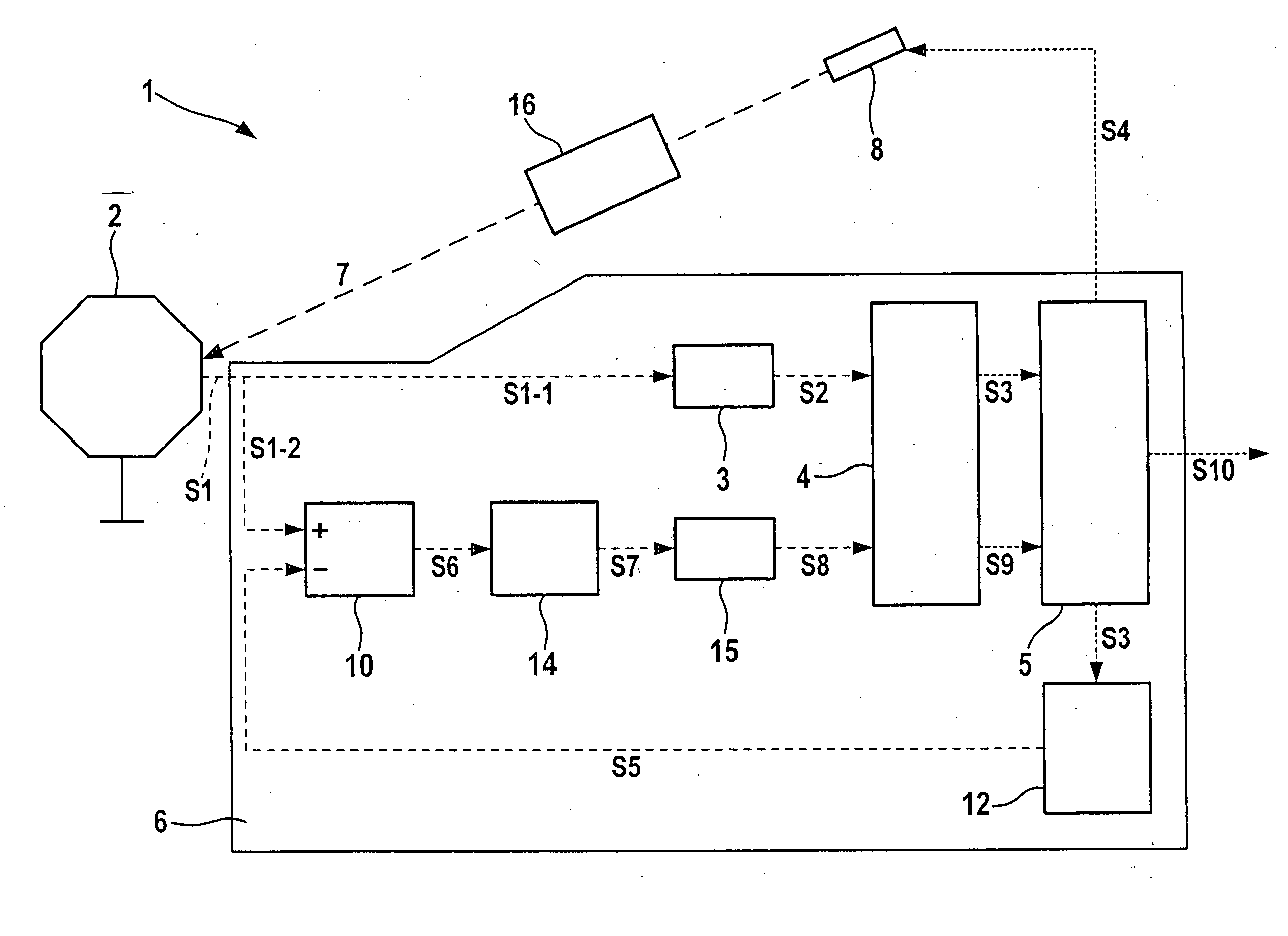
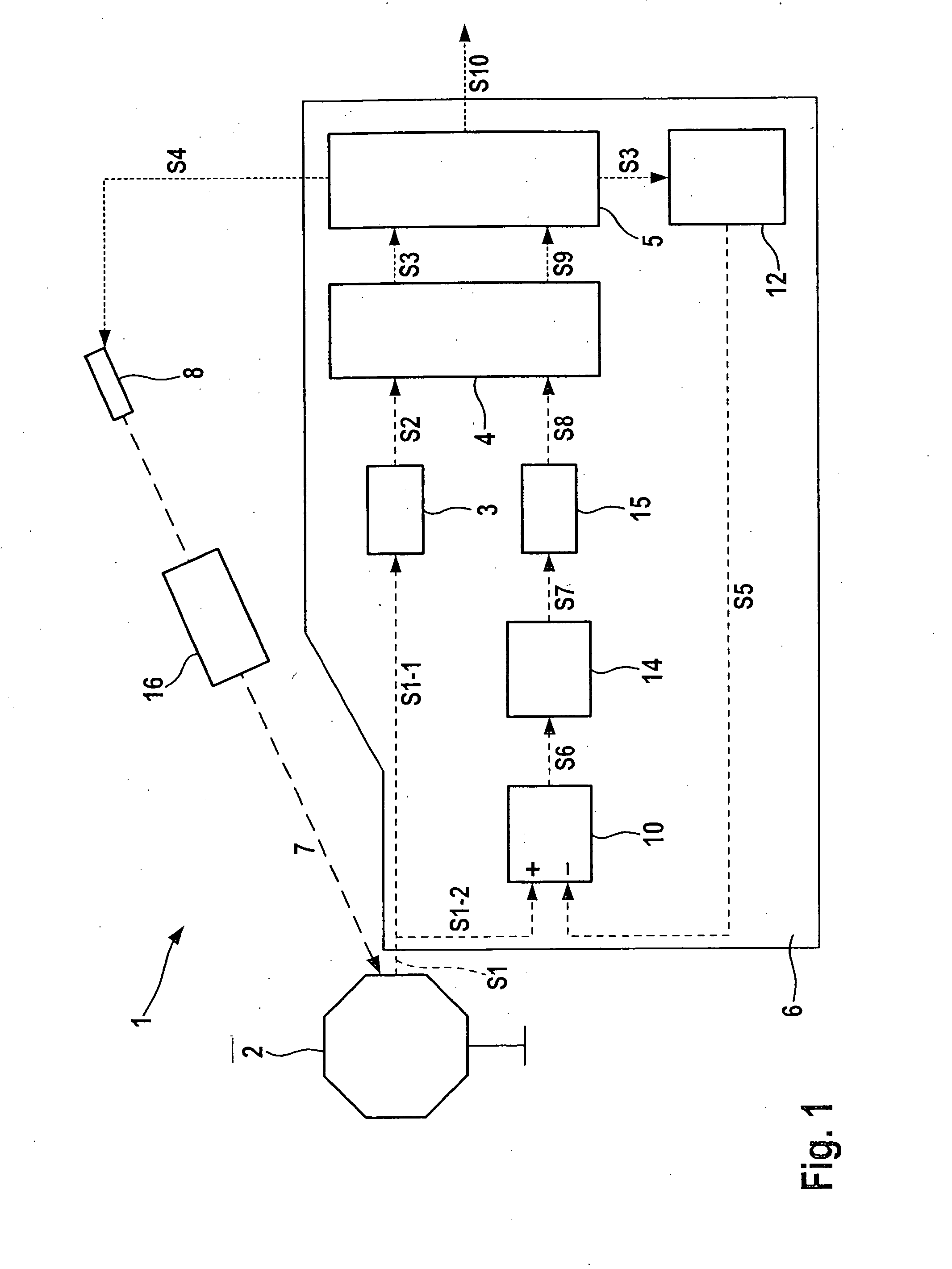
[0017]A measuring device 1, shown in FIG. 1, is used for measuring the intensity of incident IR radiation 7. It has a detector 2 which receives incident IR radiation 7. Detector 2 is advantageously a pyroelectric detector which heats up as a function of the intensity of incident IR radiation 7, and emits a measuring signal S1, as the analog voltage signal, as a function of its temperature. Furthermore, however, detector 2 may also be a thermopile sensor, for example, which is formed, for instance, by a cascading of a plurality of thermopile elements, which are each formed by the contacting of printed circuit traces made of materials having different Seebeck coefficients, and which generate analog measuring signal S1 as a function of the temperature differences of their contact points. Moreover, detector 2 may also carry out a bolometric measurement.

[0018]Detector 2 passes analog measuring signal S1 to an evaluation device 6 according to the present invention, which include component...


PUM

PropertyMeasurementUnit
concentrationaaaaaaaaaa
temperatureaaaaaaaaaa
Seebeck effectaaaaaaaaaa

Abstract

An evaluation device for evaluating analog measuring signals of a detector, e.g., an IR detector, includes: an analog / digital converter device for digitally converting the analog measuring signal of the detector or an analog signal derived from the analog measuring signal into a digital measuring signal; a control device for receiving the digital measuring signal; and a subtraction device. The evaluation device receives a first analog measuring signal from a first measurement and stores the digital measuring signal formed from the first analog measuring signal, and also receives a second analog measuring signal from a second measurement. The subtraction device receives the analog measuring signal of the second measurement and an analog comparison signal formed as a function of the stored digital measuring signal of the first measurement, and forms a differential signal.

Description

BACKGROUND OF THE INVENTION[0001]1. Field of the Invention[0002]The present invention relates to an evaluation device and a method for evaluating analog measuring signals of a detector.[0003]2. Description of Related Art[0004]In spectroscopic gas sensor technology, various detectors and methods are used for converting infrared radiation (IR radiation) to electrical voltage signals, in which the IR radiation is absorbed, and the temperature is ascertained that sets in as a function of the intensity of the incident IR radiation. In thermopile elements the Seebeck effect is used. In a pyroelectric detector the pyroelectric effect is utilized, in which an electric voltage is generated in a piezoelectric crystal, which assumes different values at different temperatures. The analog measuring signal is generally picked up by an evaluation device, which has an analog / digital converter device for the digitization of the analog measuring signal or of the amplified analog signal, and furthermo...

Claims


Application Information

Patent Timeline
Patent Type & Authority Applications(United States)
IPC IPC(8): G01N21/35H04B15/00G01J5/30G01J5/02
CPCG01N21/3504G01N21/274
Inventor KOOP, PAULDITTMER, HELGE
Owner ROBERT BOSCH GMBH
Why Eureka
Try Eureka