
Lookdown zone mask for intrusion detector

a lookdown zone and detector technology, applied in the field of intrusion detector systems, can solve the problems of inability to remasked the lookdown zone, the area directly below the sensor is typically out of the range of the detector, and certain environments are more susceptible to false alarms, so as to prevent unauthorized tampering of the unit, prevent unauthorized tampering, and facilitate access

Active Publication Date: 2010-09-23
BOSCH SECURITY SYST INC +1
View PDF9 Cites 29 Cited by
  • Summary
  • Abstract
  • Description
  • Claims
  • Application Information

AI Technical Summary

Benefits of technology

[0018]An advantage of the present invention is the easy accessibility provided to enable and disable a lookdown zone in an intrusion detector unit.
[0019]Another advantage is the reusability of the mask or cover to selectively provide a lookdown zone at the desire of an end user without destroying an existing mask or requiring application of a new mask which may require disassembly of the entire unit.
[0020]Yet another advantage is that the lookdown zone is selectively enabled or disabled without requiring access to the interior of the detector unit, thereby helping to prevent unauthorized tampering of the unit and maintaining the integrity of the unit as a whole by preventing damage to internal components thereof. For example, exposure of the printed circuit board of the unit is advantageously prevented when changing the state of the lookdown zone.
[0021]Still another advantage is the ability to retrofit existing intrusion detector units with a mask according to the several embodiments disclosed herein.

Problems solved by technology

Although most of the areas of the room can be protected with this arrangement, the area directly below the sensor is typically out of range of the detector.
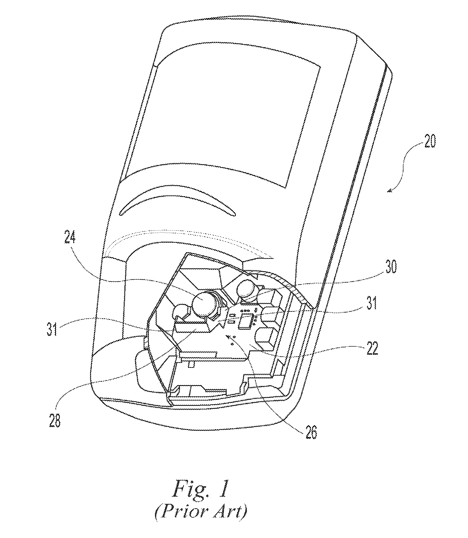
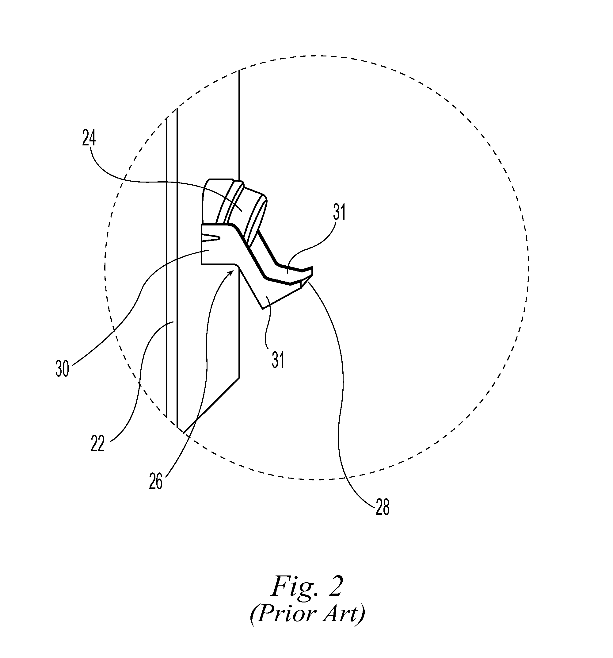
While the arrangement of FIGS. 1 and 2 offers better protection than an intrusion detector system without a lookdown zone capability, certain environments are more susceptible to false alarms when the lookdown zone is enabled in the motion sensor.
Once the installer or end user has removed and discarded the tape or paper used to mask the lookdown zone, however, the lookdown zone cannot be remasked should the environment change and / or false alarms become a problem without risking damage to other components of the intrusion detector unit, for example, the printed circuit board.
Such an operation similarly risks damage to the printed circuit board and other internal components of the intrusion detector unit.
Damage to any internal components of the unit and / or disassembly and reassembly of the unit may undesirably make the intrusion detector unit less effective, completely inoperable, or more susceptible to tampering by an intruder.

Method used


Image

  • Lookdown zone mask for intrusion detector
  • Lookdown zone mask for intrusion detector
  • Lookdown zone mask for intrusion detector

Examples


Embodiment Construction

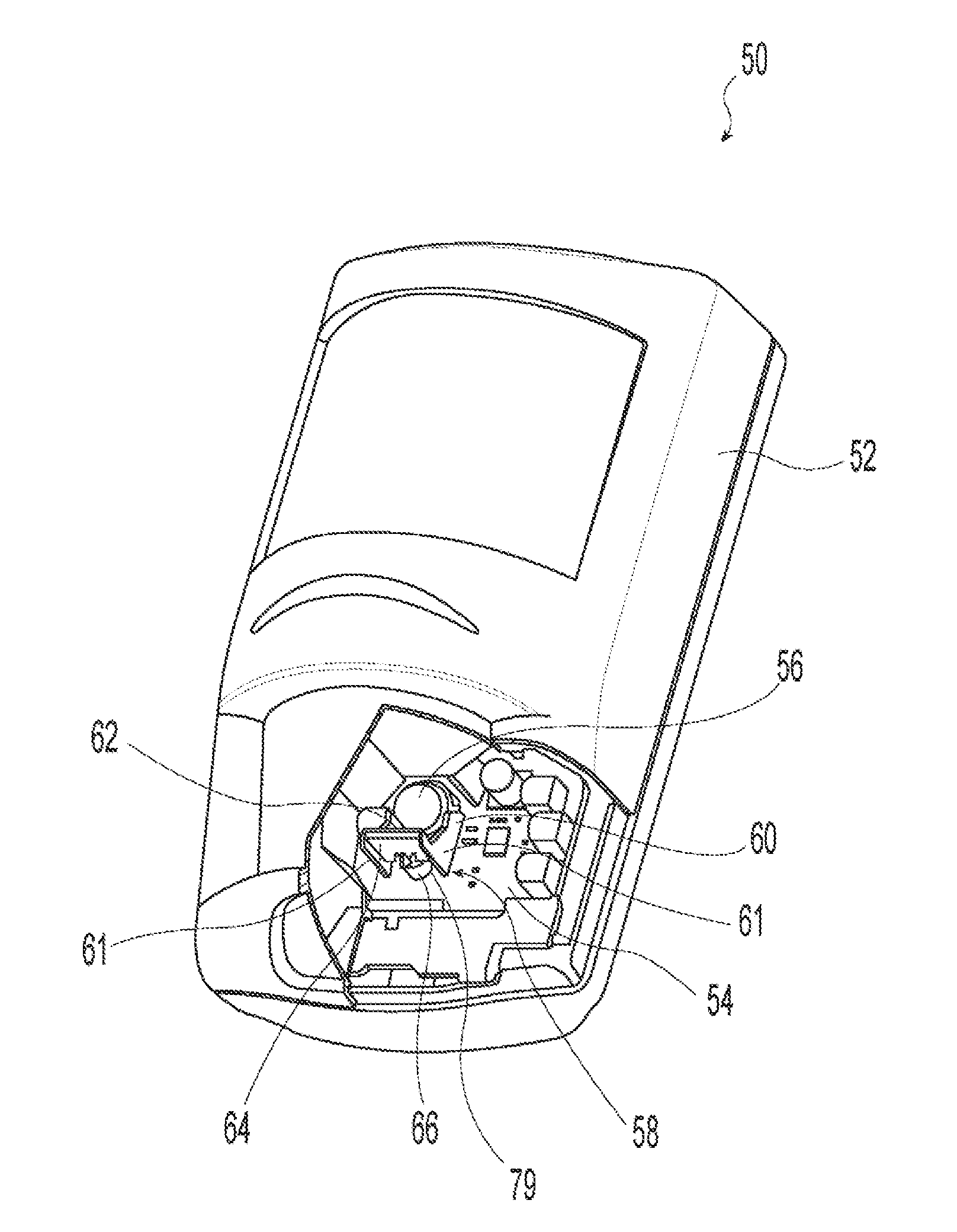
[0040]Referring now to the drawings, and particularly to FIG. 4, motion sensor or intrusion detector unit 50 is shown and includes housing 52, printed circuit board (PCB) or substrate 54, detector 56, and lens assembly 58. Lens assembly 58 may include mounting structure 60 and lens 62. In an exemplary embodiment, detector 56 is a passive infrared motion detector.

[0041]As shown in FIGS. 4-6 and 10, lens assembly 58 provides for mounting of lens 62 and detector 56 in a given and constant relationship relative to each other. In one embodiment, lens 62 may be formed as a Fresnel lens, i.e., lens 62 is flat on one side facing detector 56 and ridged on the other side facing away from detector 56. Lens 62 provides a lookdown zone capability to unit 50 to add greater protection to the area directly below unit 50 by allowing imaging of a small area almost directly therebelow. Mounting structure 60 may include two side supports 61 attached to PCB 54. Side supports 61 each include aperture 63 ...


PUM


Abstract

An apparatus for enabling and disabling a lookdown zone mask in an intrusion detector unit. The unit may include a passive infrared motion detector, a lens assembly, and a mask or cover which selectively enables and disables a lookdown zone associated with the detector. The lens assembly provides a lens proximate the detector. The lens provides the lookdown zone. When the mask substantially covers the lens, the lookdown zone is disabled because the path of radiant energy to the detector is blocked and prevents the detector from detecting any motion in the lookdown zone. When the mask does not cover the lens, the lookdown zone is enabled because the lens permits the path of radiant energy to the detector through the lens and allows the detector to detect any motion in the lookdown zone.

Description

BACKGROUND[0001]1. Field of the Invention[0002]The present invention relates to an intrusion detector system, and, more particularly, to an apparatus for enabling and disabling a lookdown zone mask in an intrusion detector unit.[0003]2. Description of the Related Art.[0004]Passive infrared (PR) motion sensors are well-known. PIR motion sensors are useful due to less susceptibility to false alarms as compared to other technologies, for example, ultrasonic and microwave motion sensors. PIR motion sensors have no active component which is radiated from the unit, such as sound or radio waves, for their operation. In general, a PIR motion sensor is typically mounted on a wall or ceiling and protects a room or other area by imaging multiple areas of the room onto an infrared detector. The output of the detector is amplified and processed for alarm output from the motion sensor.[0005]Prior PR motion sensors use a single Fresnel lens array or minor array to focus multiple areas of the room ...

Claims


Application Information

Patent Timeline
IPC IPC(8): H01L31/0232H01L31/09
CPCG08B29/18G08B13/193
Inventor WALTERS, ROBERT E.DIPOALA, WILLIAM S.
Owner BOSCH SECURITY SYST INC
Learn More