Supercharge Your Innovation With Domain-Expert AI Agents!

Permanent magnet machines

Inactive Publication Date: 2010-09-23
GENERA MOTORS LLC +1
View PDF6 Cites 4 Cited by
  • Summary
  • Abstract
  • Description
  • Claims
  • Application Information

AI Technical Summary

Benefits of technology

[0006]Permanent magnet machines are provided. In accordance with an embodiment, by way of example only, a permanent magnet machine includes a rotor and a stator, the stator including plurality of stator pole sections disposed circumferentially around the stator. Each stator pole section comprises a core section extending axially along the stator, an inner end piece disposed adjacent to the core section, the inner end piece comprising a first magnetic material that is adapted to saturate during exposure to a first magnetic field strength, and an outer end piece disposed adjacent to the core section radially outwardly relative to the inner end piece, the outer end piece comprising a second magnetic material that is adapted to be unsaturated during exposure to the first magnetic field strength and to saturate during exposure to a second magnetic field strength, wherein the second magnetic field strength is greater than the first magnetic field strength.
[0007]In acco

Problems solved by technology

Generally, a back EMF may undesirably reduce operational efficiency of the PM machine.
In particular, additional components may be included in the PM machine in order to supply the demagnetizing current, which may undesirably increase weight and size of the PM machine.
Moreover, supplying the demagnetizing current to the PM machine may direct energy resources to non-torque producing currents.
Additionally, the rotational speed of the PM machine may be limited by the amount of demagnetizing current that may be supplied to counteract the back EMF.

Method used


Image

  • Permanent magnet machines
  • Permanent magnet machines
  • Permanent magnet machines

Examples


Embodiment Construction

[0014]The following detailed description is merely exemplary in nature and is not intended to limit the invention or the application and uses of the invention. Furthermore, there is no intention to be bound by any expressed or implied theory presented in the preceding technical field, background, brief summary or the following detailed description.

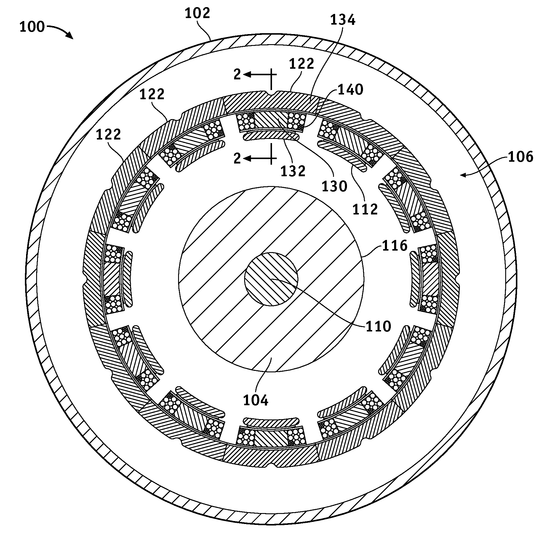
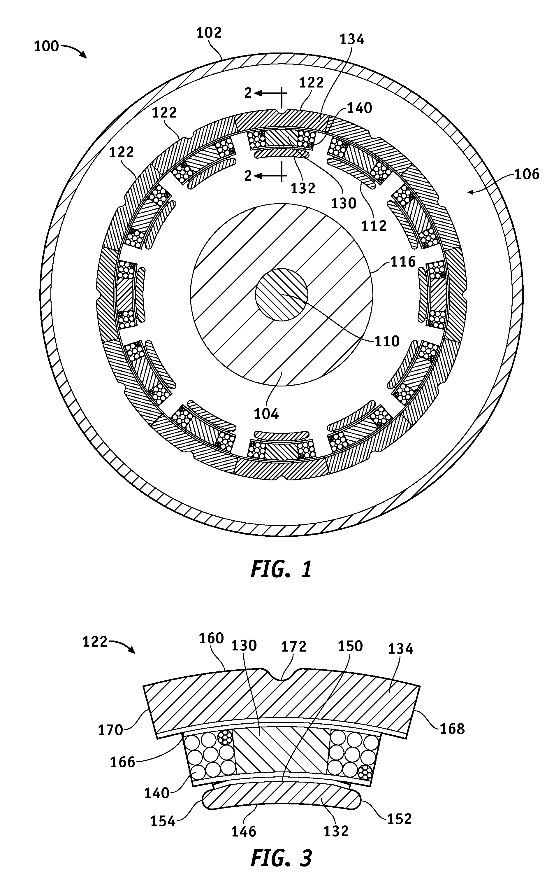
[0015]FIG. 1 is a cross-sectional end view of a simplified permanent magnet motor 100, according to an embodiment. The permanent magnet motor 100 may be a direct current (DC) motor, an alternating current (AC) motor, or another type of motor in which permanent magnets may be employed. The permanent magnet motor 100 includes a housing 102, a rotor 104, and a stator 106. The rotor 104 is disposed within the housing 102 and is mounted to a rotatable shaft 110. The stator 106 surrounds the rotor 104 and is disposed between the rotor 104 and the housing 102. In an embodiment, an inner surface 112 of the stator 106 and an outer surface 116 of th...


PUM


Abstract

A permanent magnet machine includes a rotor and a stator including plurality of stator pole sections. Each stator pole section comprises a core section having an inner end piece disposed adjacent to the core section, the inner end piece comprising a first magnetic material that is adapted to saturate during exposure to a first magnetic field strength, and an outer end piece disposed adjacent to the core section radially outwardly relative to the inner end piece, the outer end piece comprising a second magnetic material that is adapted to be unsaturated during exposure to the first magnetic field strength and to saturate during exposure to a second magnetic field strength, wherein the second magnetic field strength is greater than the first magnetic field strength.

Description

TECHNICAL FIELD[0001]The present invention generally relates to permanent magnet machines, and more particularly relates to stators for use in permanent magnet machines.BACKGROUND[0002]Alternating current (AC) motors are used in a variety of applications. To power an AC motor, a current is typically supplied to the AC motor via a direct current (DC) bus voltage source, such as a battery. The current flows through windings in a stator or a rotor of the AC motor to produce a magnetic field. The current flow creates a torque within the AC motor causing the rotor to rotate and to thereby produce mechanical power. To reduce unwanted torque pulsations in the AC motor resulting from harmonics which may be present in the AC motor during current input, a voltage source inverter is used to transform the current from the DC bus voltage source into a sinusoidally-shaped motor phase current.[0003]In some cases, the AC motor may be a permanent magnet (PM) machine. Typically, as the speed of the P...

Claims


Application Information

Patent Timeline
IPC IPC(8): H02K1/14
CPCH02K1/148H02K1/02
Inventor ALFERMANN, TIMOTHY J.MCGREW, JR., ARTHUR L.EL-ANTABLY, AHMED M.
Owner GENERA MOTORS LLC
Features
  • R&D
  • Intellectual Property
  • Life Sciences
  • Materials
  • Tech Scout
  • Unparalleled Data Quality
  • Higher Quality Content
  • 60% Fewer Hallucinations
Learn More