Piezoelectric vibrator manufacturing method, and piezoelectric vibrator, oscillator, electronic apparatus, and radio clock

a technology of piezoelectric vibrator and manufacturing method, which is applied in the direction of horology, piezoelectric/electrostrictive device details, instruments, etc., can solve the problems of unintentional lowering of the vacuum degree in the same manner, the gettering adjustment and the frequency adjustment still have following problems, etc., to improve the quality, improve the performance, and reduce the cost

Inactive Publication Date: 2010-09-23
SII CRYSTAL TECH
View PDF5 Cites 8 Cited by
  • Summary
  • Abstract
  • Description
  • Claims
  • Application Information

AI Technical Summary

Benefits of technology

[0072]According to the oscillator, the radio clock, and the electronic apparatus, since the piezoelectric vibrator improved in the quality, improved in the performance, reduced in the cost, and improved in the efficiency is provided, improvement in quality, improvement in performance, reduction in cost, and improvement in efficiency are achieved correspondingly.
[0073]According to the piezoelectric vibrator in the present invention, since the degrees of vacuum in the interiors of the cavities are extremely near under the vacuum and the adequate series resonance resistance values are secured, improvement in quality and improvement in performance can be achieved. Also, by adjusting the frequencies adequately so that the individual piezoelectric vibrating strips vibrate within the range of the nominal frequency, further improvement in quality and improvement in performance are achieved.
[0074]According to the piezoelectric vibrator manufacturing method in the present invention, since the gettering adjustment is performed while measuring the series resonance resistance values before cutting the piezoelectric vibrator wafer member, the piezoelectric vibrators described above can be manufactured at low cost with high efficiency. Furthermore, by adjusting the frequencies while measuring the frequencies before cutting the piezoelectric vibrator wafer member, the piezoelectric vibrators described above can be manufactured at a further lower cost with high efficiency.
[0075]Also, according to the oscillator, the electronic apparatus, and the radio clock in the present invention, since the piezoelectric vibrators described above are provided, improvement in quality and improvement in performance reduction in cost, and improvement in efficiency are achieved correspondingly.

Problems solved by technology

However, the adjustment of the degree of vacuum in the interior of the cavity in the related art, that is, the gettering adjustment and the frequency adjustment still have following problems, respectively.
First of all, in the gettering adjustment in the related art has the following problem.
When the gettering adjustment is performed excessively, contaminant on a surface such as the substrate on which the getter material is mounted is gasificated and fills the interior of the cavity, a phenomenon which causes the unintentional lowering of the degree of vacuum in the same manner as the case of the insufficient gettering occurs.

Method used


Image

  • Piezoelectric vibrator manufacturing method, and piezoelectric vibrator, oscillator, electronic apparatus, and radio clock
  • Piezoelectric vibrator manufacturing method, and piezoelectric vibrator, oscillator, electronic apparatus, and radio clock
  • Piezoelectric vibrator manufacturing method, and piezoelectric vibrator, oscillator, electronic apparatus, and radio clock

Examples


first embodiment

[0108]Referring now to FIG. 1 to FIG. 22, a piezoelectric vibrator manufacturing method and a piezoelectric vibrator manufactured by this manufacturing method according to a first embodiment of the present invention.

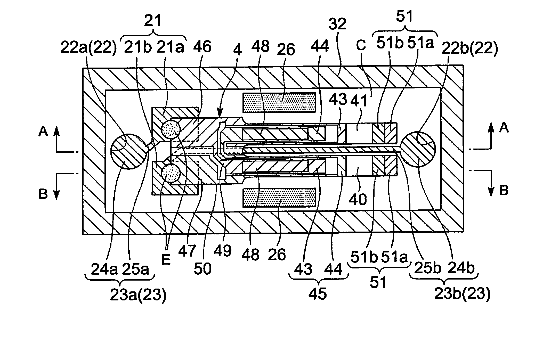
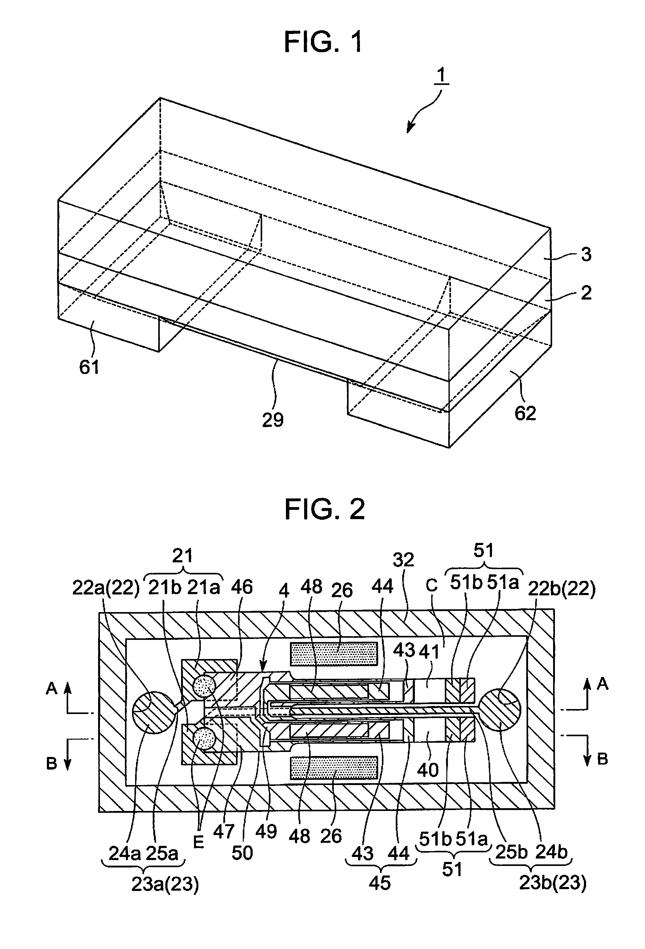
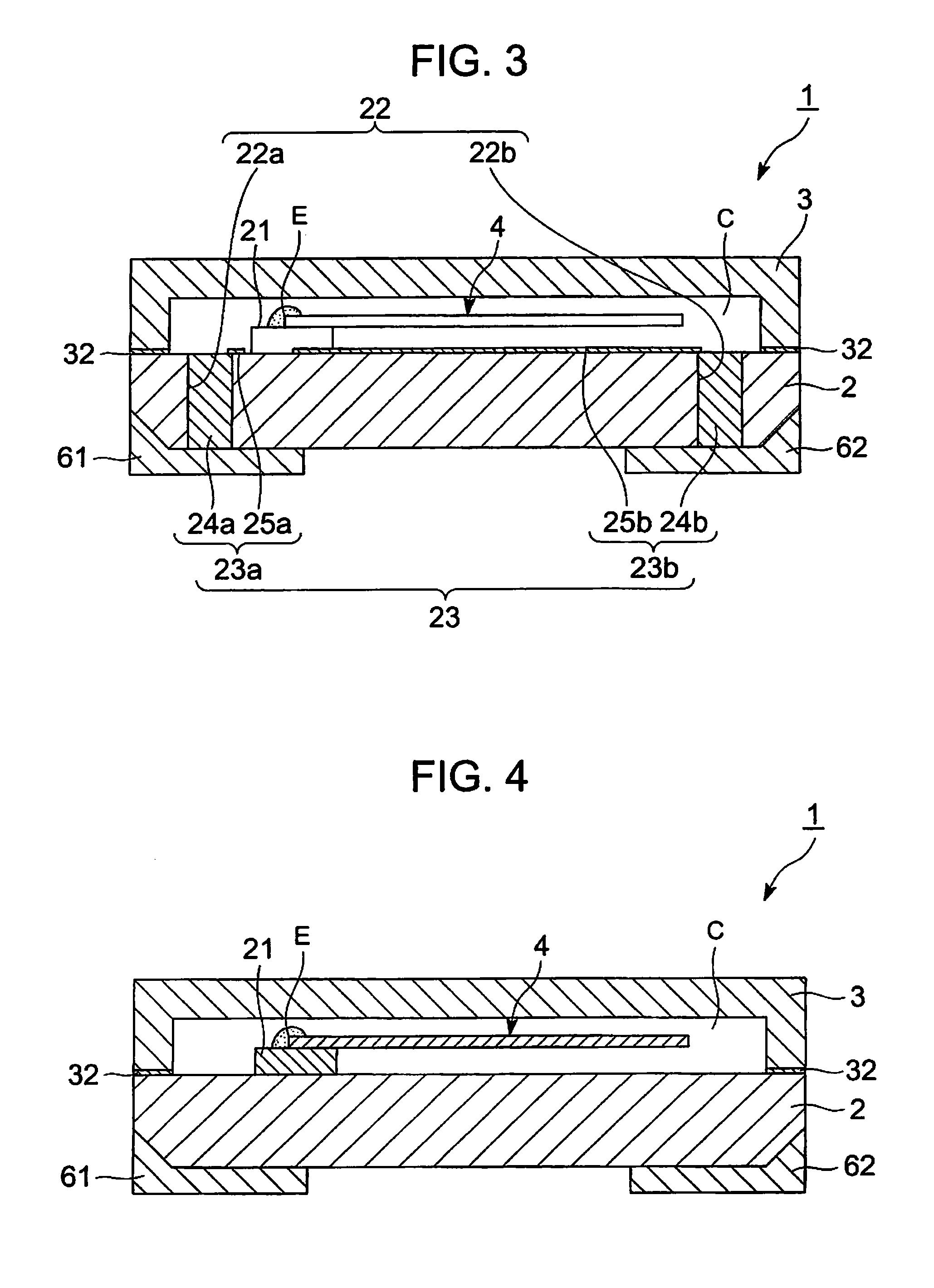
[0109]A piezoelectric vibrator 1 manufactured by the manufacturing method according to this embodiment is the piezoelectric vibrator 1 of a surface mount device type (two-layer structure type) including a piezoelectric vibrating strip 4 having a pair of mount electrodes 46, 47 electrically connected to a pair of exciting electrodes 45 encapsulated in a cavity C defined between a base substrate 2 and a lid substrate 3 which are anodically bonded with each other as shown in FIG. 1 to FIG. 5.

[0110]The piezoelectric vibrator 1 includes: a pair of mount patterns 21 formed on the base substrate 2 in the cavity C, electrically connected to the pair of mount electrodes 46, 47 respectively and supporting the piezoelectric vibrating strip 4; a bonding electrode film 32 formed on a...

second embodiment

[0161]Referring now to FIG. 23 to FIG. 26, the piezoelectric vibrator manufacturing method and the piezoelectric vibrator manufactured by this manufacturing method according to a second embodiment of the present invention will be described. In the second embodiment, the same parts as those in the first embodiment are designated by the same reference numerals and the description will be omitted, and only different points are described.

[0162]As shown in a flowchart in FIG. 23, in the piezoelectric vibrator manufacturing method in this embodiment, the external electrode forming step (S53) is performed before the gettering step (S51). The plurality of series resonance resistance values of the piezoelectric vibrating strips 4 encapsulated in the cavities C are measured simultaneously in the gettering step (S51). The piezoelectric vibrator manufactured by the manufacturing method in this embodiment is the same as the piezoelectric vibrator 1 in the first embodiment described above.

[0163]T...

third embodiment

[0191]Referring now to FIG. 27, the piezoelectric vibrator manufacturing method and the piezoelectric vibrator manufactured by this manufacturing method according to a third embodiment of the present invention. In the third embodiment, the same parts as the components in the second embodiment are designated by the same reference numerals and the description will be omitted, and only different points are described.

[0192]As shown in the flowchart in FIG. 27, in the piezoelectric vibrator manufacturing method in this embodiment, the fine adjustment step (S54) is performed after the bonding step (S43) and before the cutting step (S52). Then, the gettering step (S51) is performed prior to the fine adjustment step (S54). The piezoelectric vibrator manufactured by the manufacturing method in this embodiment is the same as the piezoelectric vibrator 1 in the second embodiment described above.

[0193]The piezoelectric vibrator manufacturing method in this embodiment will be described below.

[01...


PUM

PropertyMeasurementUnit
voltageaaaaaaaaaa
resonance frequencyaaaaaaaaaa

Abstract

A piezoelectric vibrator manufacturing method includes a cavity forming step for forming depressions for a cavities on at least one of two wafers; a bonding electrode film forming step for forming bonding electrode films on bonded surfaces of the both wafers; a mount pattern forming step for forming a pair of mount patterns in the cavity; a through hole forming step for forming a pair of through holes in the cavity; a through electrode forming step for forming a pair of through electrodes electrically connected with the pattern in the cavity; a mount step for electrically connecting the pattern and a piezoelectric vibrating strip, a superimposing step for superimposing the both wafers and storing getter materials; a bonding step for anodically bonding the both wafers to fabricating a wafer member; a gettering step for adjusting the degree of vacuum in the interior of the cavity while measuring a series resonance resistance value; and a cutting step for cutting the wafer member into individual pieces.

Description

RELATED APPLICATIONS[0001]This application is a continuation of PCT / JP2008 / 069108 filed on Oct. 22, 2008, which claims priority to Japanese Application Nos. JP2007-313513 filed on Dec. 4, 2007 and 2008-017932 filed on Jan. 29, 2008. The entire contents of these applications are incorporated herein by reference.BACKGROUND OF THE INVENTION[0002]The present invention relates to a piezoelectric vibrator manufacturing method for manufacturing a piezoelectric vibrator of a surface mount device (SMD) type in which the piezoelectric vibrator is encapsulated in a cavity formed between bonded two substrates, a piezoelectric vibrator manufactured in this manufacturing method, and an oscillator, electronic apparatus, and a radio clock having this piezoelectric vibrator.[0003]In recent years, a piezoelectric vibrator using crystal or the like is used as a time instance source, a timing source for control signals, and a reference signal source in mobile phone sets or portable information terminal...

Claims


Application Information

Patent Timeline
Patent Type & Authority Applications(United States)
IPC IPC(8): H01L41/22H01L41/053H01L41/04H01L41/23H01L41/253H01L41/311H01L41/313H01L41/338
CPCG04F5/063H03H9/1021H03H9/21Y10T29/49155Y10T29/49798Y10T29/49004Y10T29/42Y10T29/49126
Inventor OUCHI, KEIICHIHOSHI, YUKI
Owner SII CRYSTAL TECH
Why Eureka
Try Eureka