Camera body, interchangeable lens unit, and camera system

a technology of interchangeable lenses and camera bodies, applied in television systems, printing, instruments, etc., can solve the problems of difficult use of conventional camera systems and inability to use liquid crystal monitors during imaging

Inactive Publication Date: 2010-09-23
PANASONIC CORP
View PDF14 Cites 50 Cited by
  • Summary
  • Abstract
  • Description
  • Claims
  • Application Information

AI Technical Summary

Benefits of technology

[0021]With this interchangeable lens unit, the lens information includes information related to whether or not the optical system can be electrically driven in the optical axis direction, and this lens information is stored in the memory unit. Accordingly, the camera body can decide whether or not to operate the drive of the optical system on the camera body side on the basis of lens information, and this ensures compatibility with more camera bodies.

Problems solved by technology

However, when a conventional single lens reflex reflecting mirror is used, a liquid crystal monitor cannot be used during imaging.
Since imaging cannot be performed by using a liquid crystal monitor, the user has to look through the viewfinder during imaging, so conventional camera systems have been extremely difficult to use, especially for novices who are inexperienced in using digital cameras.

Method used


Image

  • Camera body, interchangeable lens unit, and camera system
  • Camera body, interchangeable lens unit, and camera system
  • Camera body, interchangeable lens unit, and camera system

Examples


first embodiment

1: Overall Configuration of Camera System

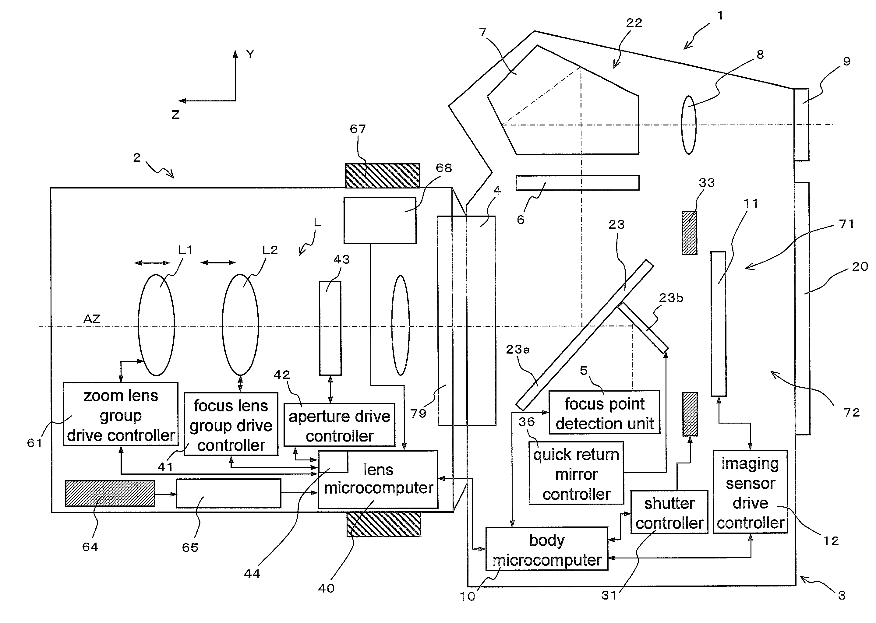
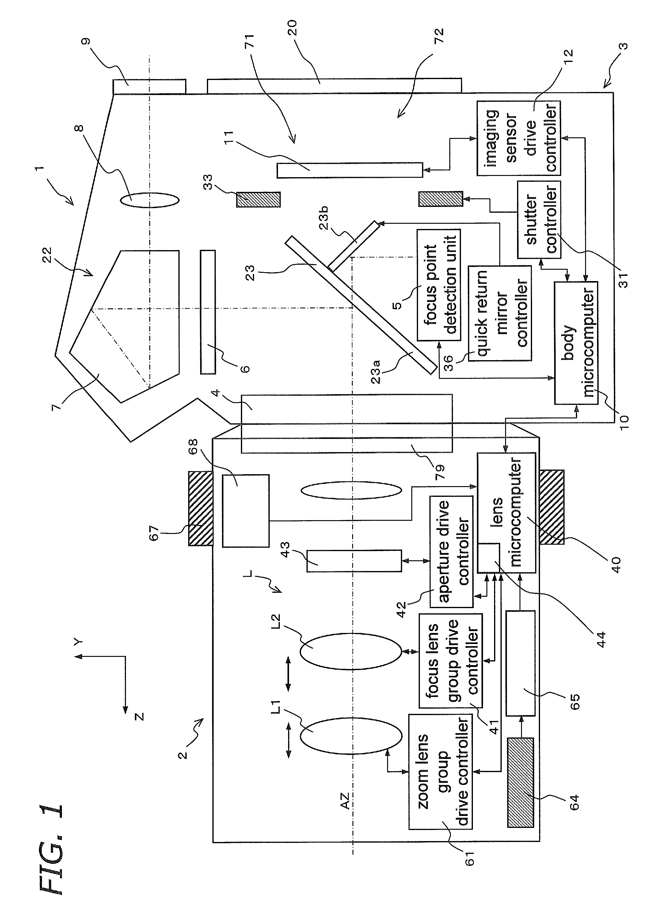
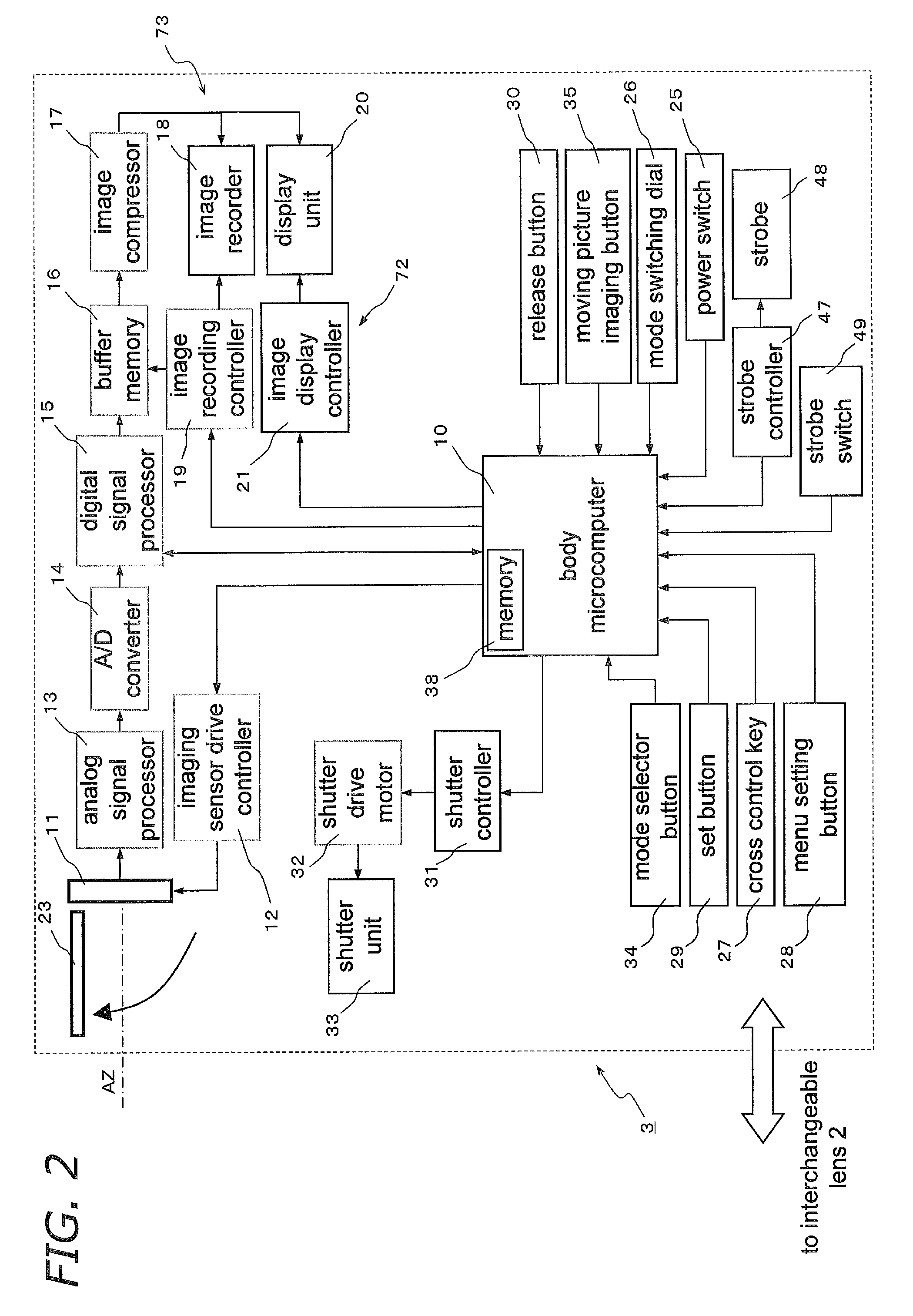
[0081]The overall configuration of the camera system 1 according to a first embodiment will be described through reference to FIGS. 1 to 3. FIG. 1 is a block diagram of the camera system 1. FIG. 2 is a block diagram of a camera body 3. FIGS. 3A and 3B are simplified diagrams the camera body 3, with FIG. 3A being a view of the camera body 3 from above, and FIG. 3B a view of the camera body 3 from the rear.

[0082]As shown in FIG. 1, the camera system 1 is an interchangeable lens type of digital single lens reflex camera system, and is made up mainly of the camera body 3 having the primary function of the digital camera 1, and an interchangeable lens unit 2 that is removably mounted to the camera body 3. The interchangeable lens unit 2 is mounted to a body mount 4 provided to the front face of the camera body 3, via a lens mount 79.

[0083]1.1: Interchangeable Lens Unit

[0084]As shown in FIGS. 1 and 2, the camera body 3 is made up mainly of an imagi...

second embodiment

[0242]There is no problem when the autofocus imaging mode is selected as the focus imaging mode.

[0243]However, if the interchangeable lens unit 2 is compatible with electric manual focus, focusing must be performed by an operation unit on the camera body 3 side. Also, if the focus ring 67 or another such focus operation unit is mounted to the interchangeable lens unit 2, damage to the system must be prevented just as with the electric zoom discussed above.

[0244]In view of this, just as in the first embodiment, a constitution is possible in which focus operation with the cross control key 27 or the focus ring 67 is either activated or inactivated according to whether or not the interchangeable lens unit 2 is compatible with electric focus (more precisely, electric manual focus).

[0245]In the following description, those components having substantially the same function as components in the first embodiment will be numbered the same and will not be described in detail again.

[0246]1: Ov...

third embodiment

[0332]The quick return mirror 23 was used in the first and second embodiments, but if focusing is possible by contrast detection method, the quick return mirror 23 can be eliminated. A camera system 1A according to a second embodiment will be described through reference to FIG. 18. FIG. 18 is a block diagram of the configuration of the camera system 1A. Those components that have substantially the same function as the components shown in FIG. 1 will be numbered the same and will not be described in detail again.

[0333]1: Overall Configuration of Camera System

[0334]In FIG. 18, the camera system 1A is a digital single lens reflex camera system with an interchangeable lens, and mainly comprises a camera body 3A having the main functions of the camera system 1A, and an interchangeable lens unit 2 that is removably mounted to the camera body 3A. The interchangeable lens unit 2 is mounted via a lens mount 79 provided at the rearmost part, to a body mount 4 provided to the front face of the...


PUM


Abstract

A camera body 3 includes a cross control key 27 and a body microcomputer 10. The body microcomputer 10 can acquire lens information related to an interchangeable lens unit 2 from the interchangeable lens unit 2. The body microcomputer 10 decides whether or not the interchangeable lens unit 2 is compatible with electric zoom on the basis of lens information. The body microcomputer 10 also activates zoom operation at the cross control key 27 on the basis of this decision result.

Description

TECHNICAL FIELD[0001]The present invention relates to an interchangeable lens type of camera body, to an interchangeable lens unit, and to a camera system.BACKGROUND ART[0002]Digital cameras with interchangeable lenses have surged in popularity in recent years. With these digital cameras, when the user looks at a subject through a viewfinder, the optical path of light that is incident on an imaging lens (that is, the subject image) is changed by a reflecting mirror disposed along the imaging optical path beyond the lens, and the light goes through a pentaprism, etc., and is converted into an erect image, and then is guided to an optical viewfinder. This allows the user to see the subject image that has passed through the lens through the optical viewfinder. Therefore, the position at which the viewfinder optical path is formed is usually the home position of the reflecting mirror.[0003]On the other hand, when a lens is used for imaging, the reflecting mirror instantly changes its po...

Claims


Application Information

Patent Timeline
Patent Type & Authority Applications(United States)
IPC IPC(8): H04N5/76H04N5/225H04N5/232H04N5/222H04N5/262
CPCG02B7/102G03B5/00G03B13/06G03B17/02H04N5/23296G03B17/20H04N5/232H04N5/23212H04N5/23293G03B17/14H04N23/673H04N23/633H04N23/69
Inventor HONJO, KENICHIUEDAYUMIKI, NAOTOKATSUYAMA, NORIKAZU
Owner PANASONIC CORP
Why Eureka
Try Eureka