Optical disc apparatus

a technology of optical discs and decoders, applied in the field of optical disc apparatuses, can solve the problems of inability inability to implement a plurality of viterbi decoders, and potential loss of trust in the whole system in the market, so as to ensure read compatibility and ensure read compatibility

Inactive Publication Date: 2006-04-27
HITACHI CONSUMER ELECTRONICS CORP
View PDF19 Cites 21 Cited by
  • Summary
  • Abstract
  • Description
  • Claims
  • Application Information

AI Technical Summary

Benefits of technology

[0048] As described above, the invention can achieve the two objects thereof and provide an optical disc apparatus implementing PRML that is capable of recording and reading a plurality of disc media with different recording densities and ensuring read compatibility between drives without relying solely on the error correction capacity of ECC.
[0049] In accordance with the optical disc apparatus of the invention, the aforementioned two objects can be achieved, whereby a plurality of disc media with different recording densities can be recorded and read and whereby read compatibility can be ensured.

Problems solved by technology

Thus, if the difference in performance of the binarizing unit exceeds the error correction performance margin, this could lead to a failure to ensure the read compatibility.
If that happens, trust in the whole system in the market could potentially be lost.
The conventional method as disclosed in JP Patent Publication (Kokai) No. 11-328860 A (1999) whereby a plurality of Viterbi decoders are implemented is not practical because the circuit size increases as the generation advances.
The conventional methods disclosed in JP Patent Publication (Kokai) Nos. 2002-175673 A and 10-172250 A (1998) lead to new problems that the size of circuits, which are complex and required to operate at high speed, increases, and that the phase margin of the PLL becomes narrowed due to the delay in the circuits.
The method of JP Patent Publication (Kokai) No. 2000-182335 A is complex in structure and requires high-speed operations and leads to an increase in circuit sizes, for example.

Method used


Image

  • Optical disc apparatus
  • Optical disc apparatus
  • Optical disc apparatus

Examples


embodiment 1

[0075] In the present embodiment, the structure of a PLL circuit will be described in concrete terms. FIG. 16 shows the structure of a phase comparator of the 2-time scheme built inside a PLL circuit of the invention. The structure is characterized in that the magnitude of the input signal at each time is also considered upon detection of an edge, while conventionally the phase comparator determines the edge solely from the sign of the input signal at two times. Namely, in order to avoid detecting an erroneous edge as described above with reference to the objects of the invention, the absolute values of the input signals x(n) and x(n−1) at two times are compared with a certain predetermined threshold value VT, and an edge is recognized only when both exceed the threshold value. In other words, an additional condition |x(n)|>VT and |x(n−1)|>VT for an edge is provided.

[0076] The operation of the phase comparator shown in FIG. 16 will now be described. In this example, the sign and ma...

embodiment 2

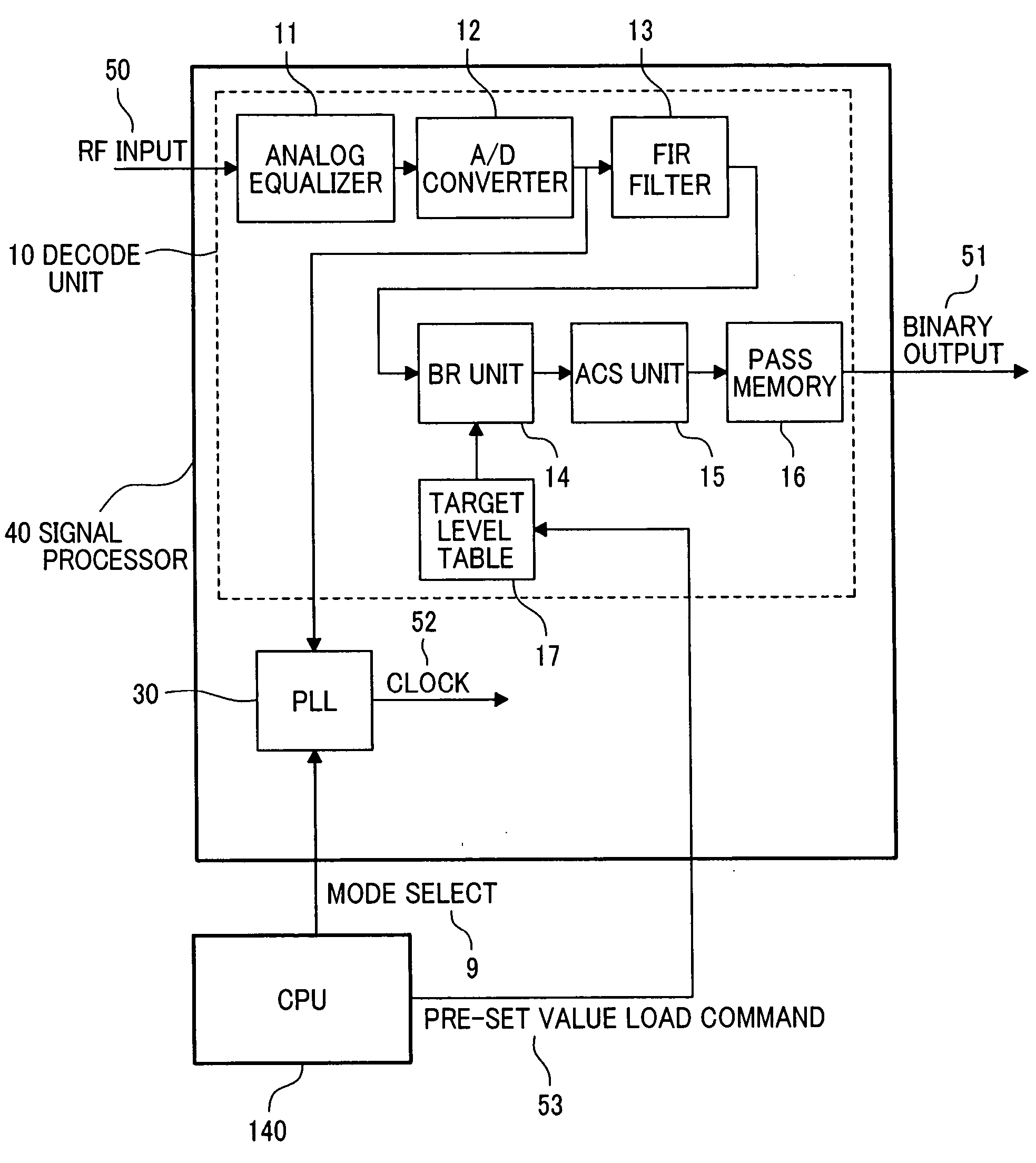
[0094] The present embodiment involves the decoding circuit. FIG. 1 shows the diagram of an example of the decoding circuit designed to be implemented on the optical disc apparatus of the invention. This configuration includes the aforementioned Viterbi decoder with an effectively variable constraint length, and a PLL in which the detection of phase error from the minimum run-length signal can be turned on and off. A read signal processing circuit 40 comprises a decode unit 10 and a PLL 30. The operation of the Viterbi decoding unit 10 is as described with reference to FIG. 7. The internal structure and operation of the PLL 30 are as described with reference to FIGS. 16 and 17. A CPU 140 for controlling the operation of the optical disc apparatus sends a preset value setting instruction 53 to a target level table 17 as needed, such as during a verification operation, so that a decoding operation can be carried out by effectively varying the constraint length. The CPU 140 also contro...

embodiment 3

[0096] The present embodiment involves an optical disc apparatus.

[0097]FIG. 24 shows an example of the optical disc apparatus in accordance with the invention. An optical disc medium 100 is rotated by a motor 160. When reading, a laser power / pulse controller 120 controls the current that flows in a semiconductor laser 112 within an optical head 110 such that laser light 114 with an optical intensity as instructed by the CPU 140 can be produced. The laser light 114 is focused by an objective lens 111 and forms an optical spot 101 on the optical disc medium 100. Reflected light 115 from the optical spot 101 is detected by a photodetector 113 via the objective lens 111. The photodetector 113 is made up of a plurality of separate photodetecting elements. A read signal processing circuit 130 reads the information recorded on the optical disc medium 100 using the signal detected by the optical head 110. When recording, the laser power / pulse controller 120 converts predetermined recording...


PUM

PropertyMeasurementUnit
width Twaaaaaaaaaa
recording densitiesaaaaaaaaaa
threshold valueaaaaaaaaaa

Abstract

An optical disc apparatus implementing a PRML and capable of recording and reading a plurality of disc media with different recording densities, wherein read compatibility between drives is ensured without relying solely on the error correction capability of the ECC (error correction code). A phase comparator provided in a PLL compares each value of an input signal sequence with a designated threshold value in order to determine an edge. The optical disc apparatus can record and read a plurality of disc media with different recording densities while ensuring read compatibility.

Description

CLAIM OF PRIORITY [0001] The present application claims priority from Japanese application JP 2004-306320 filed on Oct. 21, 2004, the content of which is hereby incorporated by reference into this application. CROSS REFERENCE TO RELATED APPLICATION [0002] U.S. patent application Ser. No. 10 / 774,587 is a co-pending application of this application. The content of which is incorporated herein by cross-reference. BACKGROUND OF THE INVENTION [0003] 1. Field of the Invention [0004] The present invention relates to an optical disc apparatus for recording information by forming a recording mark on a recording medium with a different physical property from that of the other portions of the medium. [0005] 2. Description of Related Art [0006] With optical discs such as CDs and DVDs in widespread use, and with the development of the next-generation optical discs utilizing blue laser being well underway, there is a continuing demand for greater capacities. Optical disc products are now available...

Claims


Application Information

Patent Timeline
Patent Type & Authority Applications(United States)
IPC IPC(8): G11B5/09
CPCG11B20/10009G11B20/10055G11B20/10101G11B20/10111G11B20/1012G11B2007/0006G11B2020/10879
Inventor MINEMURA, HIROYUKIKIKUGAWA, ATSUSHI
Owner HITACHI CONSUMER ELECTRONICS CORP
Why Eureka
Try Eureka