This helps you quickly interpret patents by identifying the three key elements:
Problems solved by technology
Method used
Benefits of technology
Benefits of technology
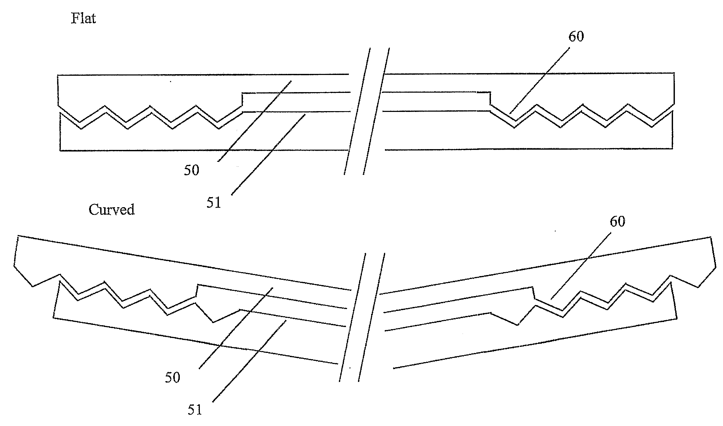
[0030]At least one second point of the light-outputting layer and at least one second point of the light-directing layer may be fixed relative to each other, after bending of the layers, so as to prevent lateral movement between the layers.
[0049]It is thus possible to provide an arrangement which may be used in backlighting technology to maintain central brightness along a preferred configurable direction, uniformity and viewing freedom even when bent to an arbitrary radius of curvature. Backlights may be provided that are capable of being bent in two directions or about an arbitrary angle including complex and facetted curve shapes.
[0051]It is possible to manufacture different fixed curve geometries from a single production line and backlight design. In addition, foldable and related e-paper display applications with flexible LCDs become possible.
Problems solved by technology
A curved display with a flat backlight may take up more space than an equivalent un-styled flat display system.
Fully flexible displays based on OLED or related technology have so far failed to have an impact on the market mainly because of lifetime and brightness issues.
However, there is no flexible lighting technology for the LCD that can maintain the brightness, viewing freedom and uniformity similar to a flat LCD for such a flexible LC display.
For such backlights, this is typically insignificant.
Thus the effect of the curve is also insignificant to the optical performance of these features.
However, the central brightness is reduced to a great extent and this is not acceptable in most applications.
There is no system in the prior art that can maintain central brightness, viewing freedom and uniformity for any arbitrary curve shape, dependent only on the shape that it is physically forced into, i.e. a fully flexible backlight.
Method used
Image
Click on the blue label to locate the original text in one second.
Reading with bidirectional positioning of images and text.
Examples
first embodiment
[0163]It is also possible to reduce the lens pitch further if it is known in advance whether the bend will be convex or concave. FIG. 19b illustrates the design for a concave only design. In the flat backlight case, the extraction features, 192, direct light, 194 not along the local normal. The slope of the extraction features is less than previously away from the light sources, and greater than normal towards the light sources. This light meets the lens, 193, off-centre, and is directed towards the viewer by the lens, 195. When the backlight is bent, the light moves across the lens and is directed properly, 195, by the lens in the manner described above. For a give bend radius the pitch of the lens need only be half the pitch of the lens in the A similar argument applies for convex only, where the slope magnitudes are reversed relative to the light source direction.
[0164]A fifth embodiment is shown in FIG. 20a and is similar to the first embodiment. Only the differences will be de...
embodiment 4
[0192]If the emission direction 244 is not along the local normal axis (cf. Embodiment 4), then the slope angles may be different (FIG. 24b), i.e. 242a and 242b are different.
[0193]An eighth embodiment is shown in FIG. 25 and can be applied to the sixth embodiment. Only the differences will be described here.
[0194]In this embodiment, light sources of the type above can be used on more than one side (and can be all four sides) of the light guide.
[0195]FIG. 25 illustrates the case of two light sources, 12a and 12b, but can also be a cross section from a four light sourcesystem. The diagram illustrates the lightguide layer, 250, the second layer, 251, and the flexible extraction features 252.
[0196]Structures that use the trapezoid structure need a slope angle, 253, which may not be the same as the previous slope angle, in a direction away from the new light source(s). The two opposing slopes, 253a and 253b, then direct light from the two light sources in the proper direction, 254.
sixth embodiment
[0197]The operation of this embodiment following bending is identical to that of the sixth embodiment as illustrated in FIG. 23.
[0198]Structures that use the segmented spheroid structures need no further modification for this backlight to operate.
PUM
Abstract
A light output arrangement is provided and may be used as a backlight for a display. The arrangement comprises a bendable light-outputting layer (51), for example, comprising a light-guide, and a bendable light-directing layer (50), for example, comprising a lens array. The layers (50, 51) are fixed together so as to prevent relative lateral movement at the mid-points but otherwise are constrained to bend in conformance with each other. The light-directing layer comprises a plurality of structures, such as lenses (81), which cooperate with, for example, light extraction features (80) in the light guide (51) so as to direct light output from the light-directing layer (50) in substantially the same direction (82, 83) irrespective of bending of the layers (50, 51).
Description
TECHNICAL FIELD[0001]The present invention relates to a light output arrangement, for example for use as a backlight for an at least partially transmissive spatial light modulator. The present invention also relates to a display including such a backlight and to a multiple view display.BACKGROUND ART[0002]WO 2006 / 137623 (Fawoo) describes a flexible light-guide made from a soft synthetic resin material that allows the light-guide to be flexible. A plurality of LED light sources at one edge and V grooves on one surface of the resin means that light is guided and extracted from the light-guide. Applications include advertisement, illumination lighting and decoration.[0003]WO 2006 / 004775 (National Semiconductor) describes a flexible touch screen light-guide made up of a coherent fiber bundle in the shape of a flat slab. Pressure from a finger or stylus brings the fibers into contact thus forming a reflective area that can be optically measured.[0004]US 2007 / 0014097 (Hong Jin Park) descr...
Claims
Application Information
Patent Timeline
Application Date:The date an application was filed.
Publication Date:The date a patent or application was officially published.
First Publication Date:The earliest publication date of a patent with the same application number.
Issue Date:Publication date of the patent grant document.
PCT Entry Date:The Entry date of PCT National Phase.
Estimated Expiry Date:The statutory expiry date of a patent right according to the Patent Law, and it is the longest term of protection that the patent right can achieve without the termination of the patent right due to other reasons(Term extension factor has been taken into account ).
Invalid Date:Actual expiry date is based on effective date or publication date of legal transaction data of invalid patent.

