[0101]First, the
Abbe number and the relative partial dispersion of an optical element are defined as follows:θd=(nd−1) / (nF−nC),θgF=(ng−nF) / (nF−nC)θhg=(nh−ng) / (nF−nC)where, nd, nC, nF, ng, and nh are the refractive indices of each optical element for a
wavelength of 587.6 nm (d-line), for a
wavelength of 656.3 nm (C-line), for a
wavelength of 486.1 nm (F-line), for a wavelength of 435.8 (g-line), and for a wavelength of 404.7 nm (h-line), νd is the
Abbe number of the optical element, θgF is the relative partial dispersion of the optical element for the g-line and the F-line, and θhg is the relative partial dispersion of the optical element for the h-line and the g-line.
[0102]Secondly, a description will be made of a cemented optical element in which two optical elements are cemented together. When the cemented optical element (in which two elements are cemented) is regarded as a single optical element, its effective relative partial dispersion eg21 can be obtained by the following equation:θgF21=f21>ν21×(θgF1×φ1 / νd1+θgF2×φ2 / ν2) (A),where f21 is the composite
focal length of the two optical elements, ν21 is the
Abbe number of the two optical elements regarded as a single optical element, θgF1 is the relative partial dispersion of one optical element, φ1 is the refracting power of the one optical element, νd1 is the Abbe number of the one optical element, θgF2 is the relative partial dispersion of the other optical element, φ2 is the refracting power of the other optical element, and ν2 is the Abbe number of the other optical element. In addition, f21, ν21, φ1, and φ2 are represented by the following equations respectively:1 / f21=1 / f1+1 / f2 ν21=1 / (f21×(φ1 / νd1+φ2 / ν2))φ1=1 / f1 φ2=1 / f2 where f1 is the
focal length of the one optical element, and f2 is the
focal length of the other optical element.
[0103]In the case of a cemented optical element in which three optical elements are cemented together, one optical element may be regarded as an optical element in which two optical elements are cemented together, and the other optical element may be regarded as the remaining one optical element. In this case, the effective relative partial dispersion eg321 of the cemented optical element (in which three elements are cemented together) regarded as a single optical element is as follows:θgF321=f321×ν321×(θgF21×φ21 / νd21+θgF3×φ3 / ν3) (B),where f321 is the composite focal length of the three optical elements, ν321 is the Abbe number of the three optical elements regarded as a single optical element, θgF21 is the relative partial dispersion of one optical element (i.e. the cemented optical element made up of two elements), φ21 is the refracting power of the one optical element (i.e. the cemented optical element made up of two elements), νd21 is the Abbe number of the one optical element (i.e. the cemented optical element made up of two elements), θgF3 is the relative partial dispersion of the other optical element, φ3 is the refracting power of the other optical element, and ν3 is the Abbe number of the other optical element.
[0104]In the following description, the relative partial dispersion will refer to the relative partial dispersion for the g-line and the F-line, unless otherwise specified.
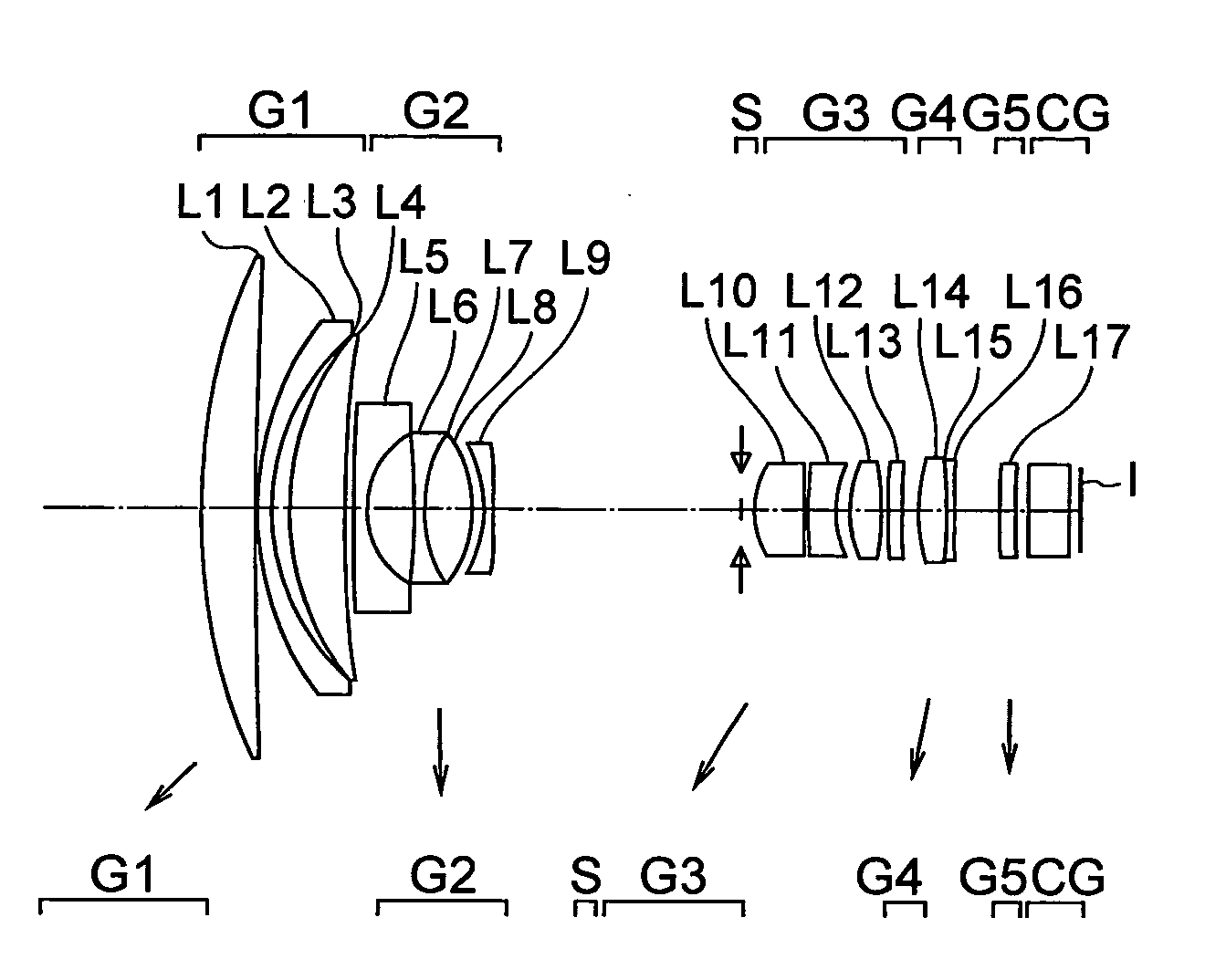
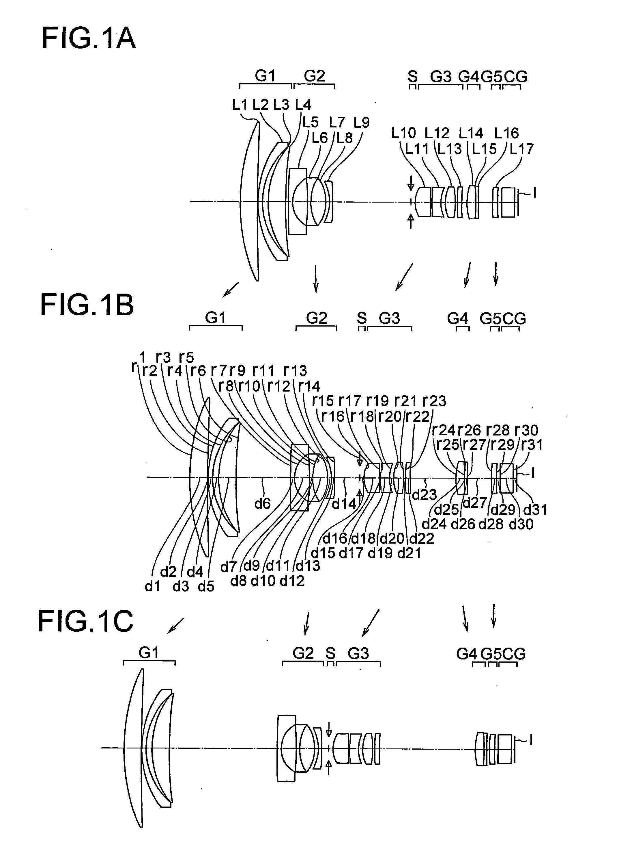
[0105]An
image forming optical system according to a first mode comprises, in order from the object side to the image side, a first lens group having a positive refracting power, a second lens group having a negative refracting power, and an image side lens group having a positive refracting power, wherein the distance between the first lens group and the second lens group changes during zooming, a cemented optical element D is provided in the first lens group, the cemented optical element being made up of an optical element B disposed on the object side, an optical element C disposed on the image side, and a refractive optical element A having a positive refracting power disposed between the optical element B and the optical element C, and there is at least one optical element having a positive refracting power located closer to the object side than the cemented optical element D, the optical
system satisfying the following conditional expressions (4-1), (4-2), and (4-3):νdA<30 (4-1)0.54<θgFA<0.9 (4-2)0.4<θgFn<0.9 (4-3)where ndA, nCA, nFA, and ngA are the refractive indices of the refractive optical element A for the d-line, the C-line, the F-line, and the g-line respectively, ndB, nCB, nFB, and ngB are the refractive indices of the optical element B for the d-line, the C-line, the F-line, and the g-line respectively, ndC, nCC, nFC, and ngC are the refractive indices of the optical element C for the d-line, the C-line, the F-line, and the g-line respectively, νdA is the Abbe number (ndA−1) / (nFA−nCA) of the refractive optical element A, νdB is the Abbe number (ndB−1) / (nFB−nCB) of the optical element B, νdC is the Abbe number (ndC−1) / (nFC−nCC) of the optical element C, νdBA is the Abbe number of the refractive optical element A and the optical element B regarded as a single optical element, θgFA is the relative partial dispersion (ngA−nFA) / (nFA−nCA) of the refractive optical element A, θgFB is the relative partial dispersion (ngB−nFB) / (nFB−nCB) of the refractive optical element B, θgFC is the relative partial dispersion (ngC-nFC) / (nFC−nCC) of the refractive optical element C, θgFBA is the effective relative partial dispersion of the refractive optical element A and the optical element B regarded as a single optical element, fA is the focal length of the refractive optical element A, fB is the focal length of the optical element B, fC is the focal length of the optical element C, fBA is the composite focal length of the optical element B and the refractive optical element A, ft is the composite focal length of the refractive optical element A, the optical element B, and the optical element C, and θgFn is the effective relative partial dispersion ft×νefn×(θgFBA×φBA / νBA+θgFC×φC / νc) of the cemented optical element D, whereinνefn=1 / (ft×(φBA / νBA+φC / νc)θgFBA=fBA×νBA×(θgFA×φA / νdAθgFB×φB / νB),νBA=1 / (fBA×(φA / νdAφB / νB),1 / fBA=1 / fA+1 / fB,φA=1 / fA,φB=1 / fB,φC=1 / fC, andφBA=1 / fBA.
[0106]In the
image forming optical system in which the first lens group has a positive refracting power, aberrations generated in the first lens group is enlarged by the second and subsequent lens groups. This will deteriorate the optical performance of the entire optical
system. In particular, chromatic aberrations will be deteriorated at the telephoto end. Therefore, in order to maintain high optical performance or to improve the optical performance, it is important that chromatic aberrations be corrected excellently in the first lens group. In view of this, in the image forming optical system according to this mode, the refractive optical element A having a positive refracting power is provided in the first lens group, and the image forming optical system is designed to satisfy conditional expressions (4-1) and (4-2), whereby chromatic aberrations generated in the first lens group, especially second order spectrum, are made small.

