Mobile imaging apparatus

a mobile imaging and apparatus technology, applied in electrical equipment, medical science, diagnostics, etc., can solve the problems of inhibiting the operator's ability to image the patient in various operational and clinical scenarios

Active Publication Date: 2010-09-23
ORTHOSCAN INC
View PDF9 Cites 40 Cited by
  • Summary
  • Abstract
  • Description
  • Claims
  • Application Information

AI Technical Summary

Benefits of technology

[0009]In an exemplary embodiment, an imaging apparatus comprises a movable cabinet, an arm assembly, an imaging arm assembly, a monitor, and a control. The arm assembly is coupled to the movable cabinet. The arm assembly also comprises a coupling configured to provide vertical movement and rotational movement. The imaging arm assembly is coupled to the arm assembly. The imaging arm also comprises an x-ray source and a sensor. The monitor is coupled to the movable cabinet and is in electronic communication with said sensor, such that the monitor is configured to display data detected by the sensor. Finally, the control is coupled to the movable cabinet and is in electronic communication with the x-ray source and is configured to operate said x-ray source.

Problems solved by technology

Limitations in the displacement of the C-arm assembly can inhibit the operator's ability to image the patient in various operational and clinical scenarios.

Method used


Image

  • Mobile imaging apparatus
  • Mobile imaging apparatus
  • Mobile imaging apparatus

Examples


Embodiment Construction

[0018]The following description is of exemplary embodiments of the invention only, and is not intended to limit the scope, applicability, or configuration of the invention in any way. Rather, the following description is intended to provide a convenient illustration for implementing various embodiments. As will become apparent, various changes may be made in the function and arrangement of the elements described in these embodiments without departing from the scope of the invention as set forth in the appended claims.

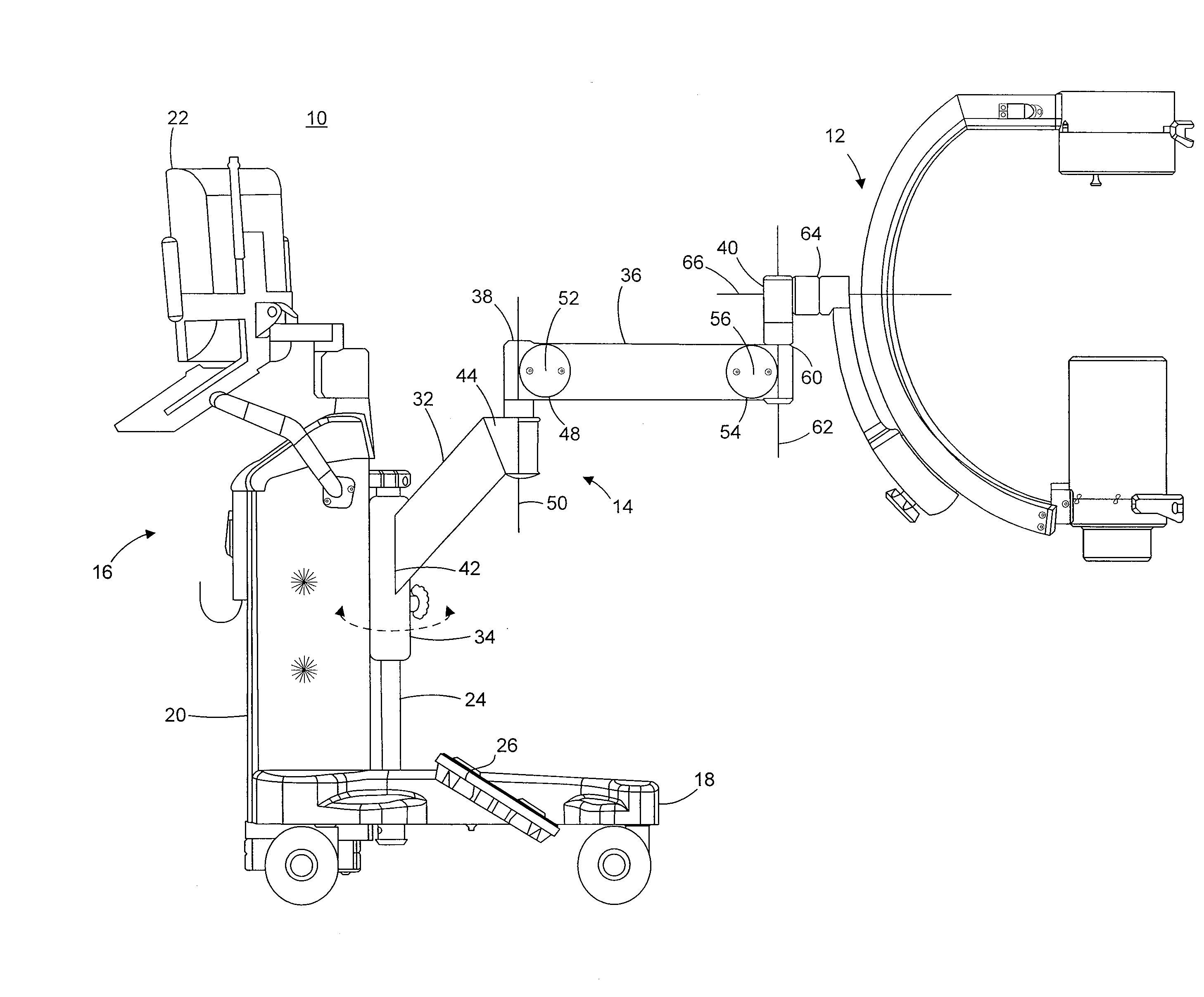
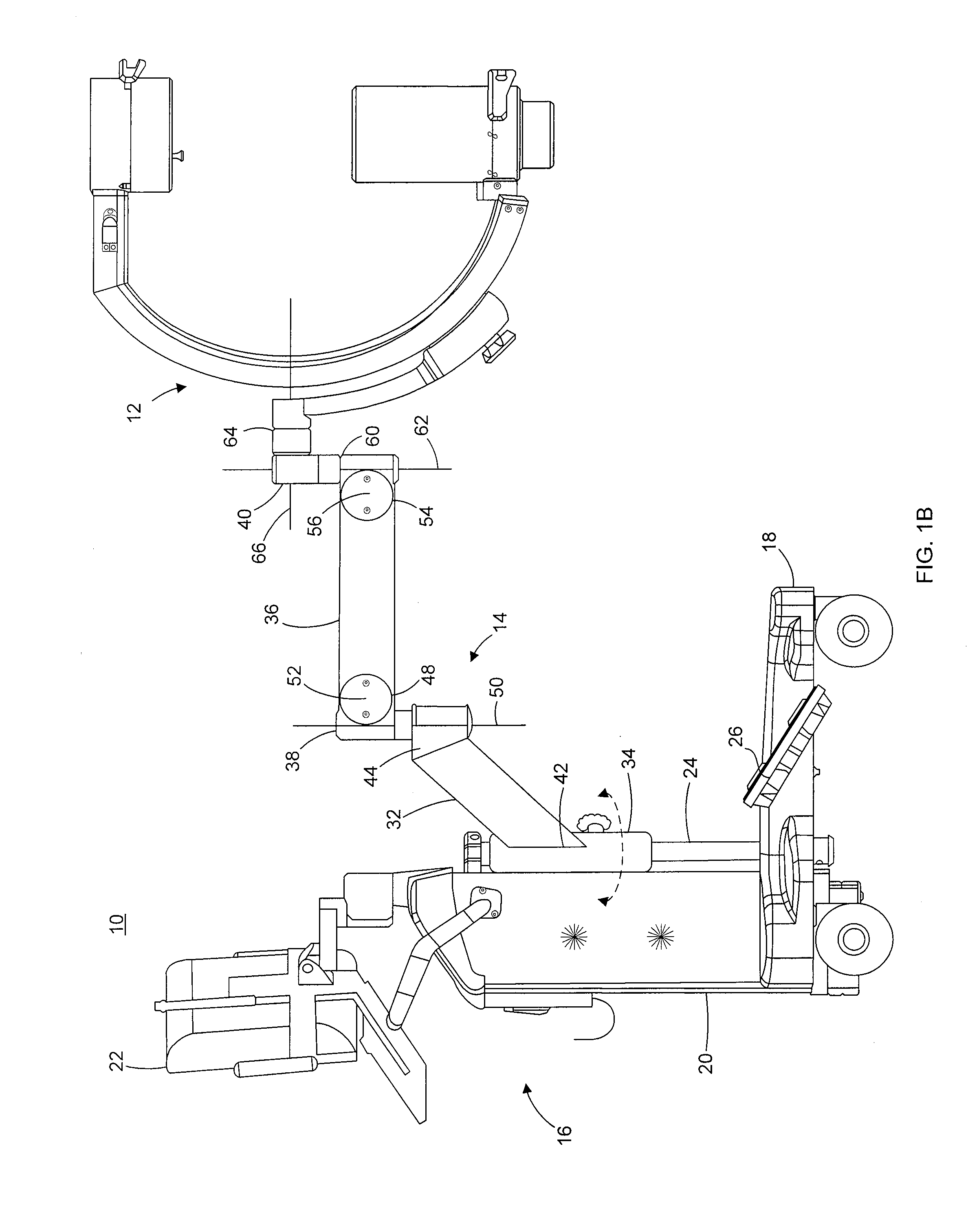
[0019]The ability to position imaging components relative to a patient can provide a convenience, a clinical advantage, and a safety advantage in that an imaging device can be made to accommodate the patient's limited mobility. As an example, when imaging a load bearing knee view in a clinical environment, the patient may be required to stand on the damaged or sore knee if the imaging assembly cannot be lowered to capture the required image while the patient is in a mor...


PUM


Abstract

In an exemplary embodiment, an imaging apparatus comprises an arm assembly coupled to an imaging arm. The arm assembly includes a shoulder joint, an elbow joint, and an articulation assembly. The shoulder joint is configured to travel a vertical distance in a substantially linear fashion and provide rotational movement. The imaging arm comprises a first end and a second end. As such, the imaging apparatus is configured to provide radial motion along a path equal to the length of the arm assembly and the imaging arm along the vertical distance and the horizontal distance of the shoulder joint. The imaging apparatus may also comprise a movable cabinet, a monitor, and a control, with the arm assembly coupled to the movable cabinet. Furthermore, the imaging arm may comprise an x-ray source and a sensor, with the monitor displaying data detected by the sensor.

Description

CROSS REFERENCE TO RELATED APPLICATION[0001]This application claims priority to U.S. Ser. No. 61 / 162,152, entitled “MINIATURE C-ARM IMAGING APPARATUS”, filed on Mar. 20, 2009, and claims priority to U.S. Ser. No. 61 / 312,104, entitled “MINIATURE IMAGING APPARATUS”, filed on Mar. 9, 2010, the entire disclosures of which are incorporated herein by reference.FIELD OF THE INVENTION[0002]The present invention generally relates to imaging systems, and, more particularly, to fluoroscopic radiographic imaging systems utilizing a miniature imaging apparatus.BACKGROUND OF THE INVENTION[0003]Fluoroscopic radiographic imaging systems provide non-invasive means of imaging bone and tissue. Fluoroscopy is the term that describes the process of obtaining multiple radiographic images at regular intervals and displaying them in sequence to create a video image of the anatomy being examined.[0004]A conventional mini imaging apparatus, such as, for example, a mini “C-arm” imaging apparatus may comprise ...

Claims


Application Information

Patent Timeline
Patent Type & Authority Applications(United States)
IPC IPC(8): H05G1/02
CPCA61B6/4233A61B6/4405H05G1/02A61B6/588A61B6/4441
Inventor EAVES, CHRISTOPHER B.
Owner ORTHOSCAN INC
Why Eureka
Try Eureka