Touch display system and control method thereof

a display system and control method technology, applied in the direction of mechanical pattern conversion, power supply for data processing, instruments, etc., can solve the problems of power key and function key size increase, fabrication etc., and achieve the effect of reducing the size and cost of the touch display system

Inactive Publication Date: 2010-09-23
CORETRONIC
View PDF5 Cites 13 Cited by
  • Summary
  • Abstract
  • Description
  • Claims
  • Application Information

AI Technical Summary

Benefits of technology

[0008]The present invention provide a touch display system ...

Problems solved by technology

The power key and function keys increase size ...

Method used


Image

  • Touch display system and control method thereof
  • Touch display system and control method thereof
  • Touch display system and control method thereof

Examples


Embodiment Construction

[0024]In the following detailed description of the preferred embodiments, reference is made to the accompanying drawings which form a part hereof, and in which are shown by way of illustration specific embodiments in which the invention may be practiced. In this regard, directional terminology, such as “top,”“bottom,”“front,”“back,” etc., is used with reference to the orientation of the Figure(s) being described. The components of the present invention can be positioned in a number of different orientations. As such, the directional terminology is used for purposes of illustration and is in no way limiting. On the other hand, the drawings are only schematic and the sizes of components may be exaggerated for clarity. It is to be understood that other embodiments may be utilized and structural changes may be made without departing from the scope of the present invention. Also, it is to be understood that the phraseology and terminology used herein are for the purpose of description an...


PUM


Abstract

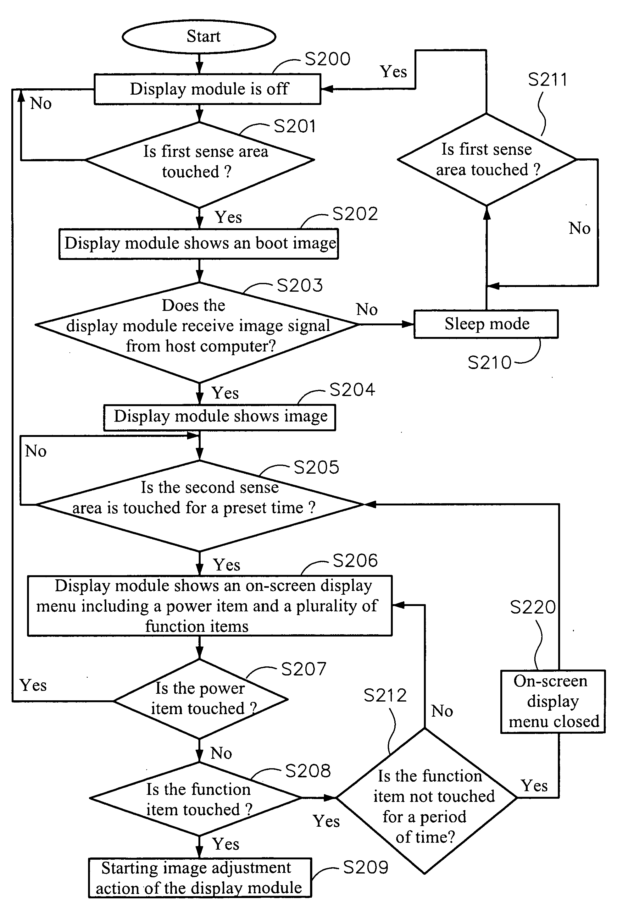
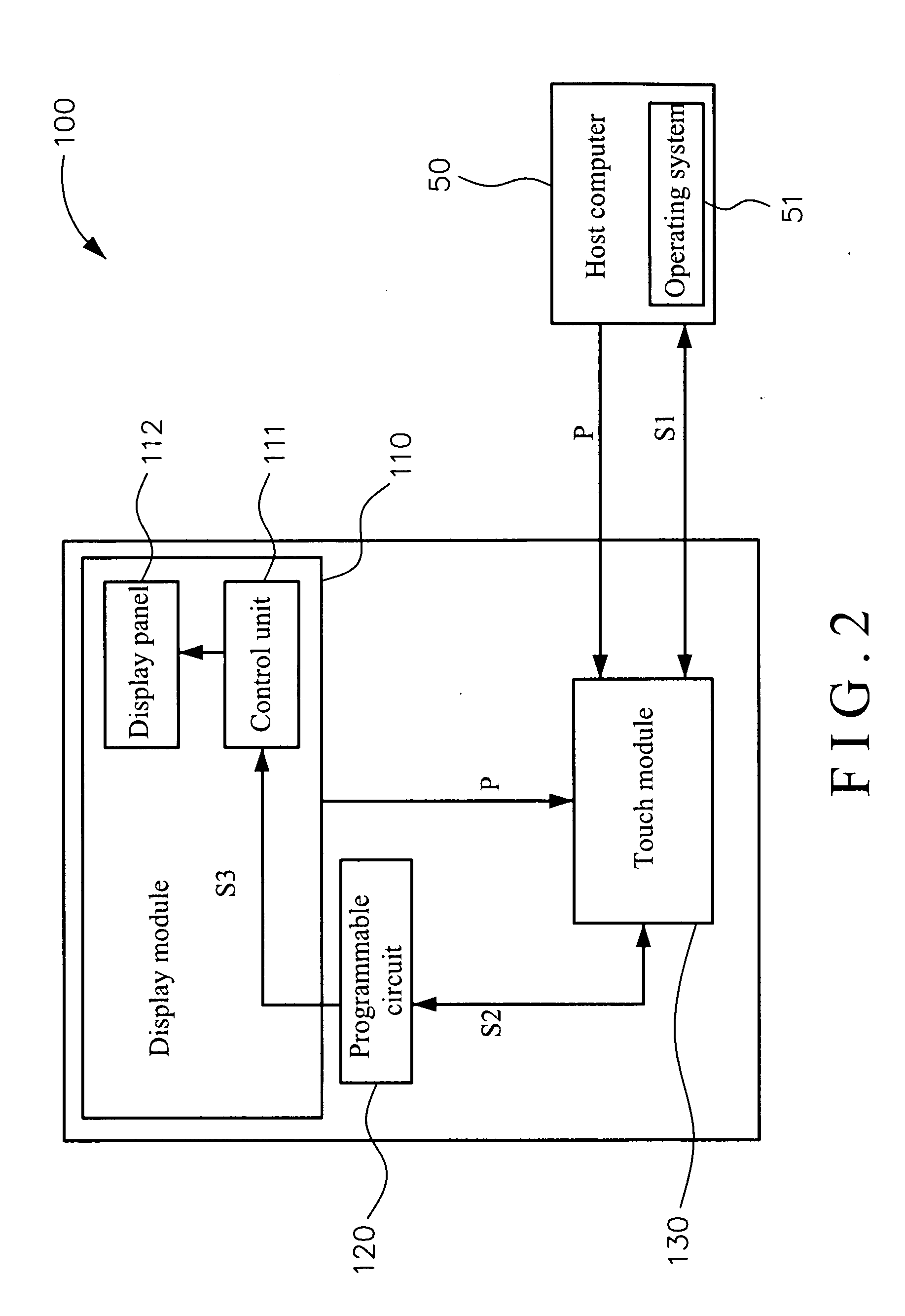
A control method is applied to a touch display system. The touch display system includes a display module, a touch module, and a programmable circuit. The programmable circuit is electrically connected between the touch module and the display module for executing the control method. The method includes: the touch module providing a first sense area; detecting whether the first sense area being touched or not; the display module displaying an boot image when the first sense area being touched; providing a second sense area after the boot image being displayed; detecting whether the second sense area being touched or not; and the display module displaying an on-screen display menu when the second sense area being touched, wherein the on-screen display menu includes a power item and a plurality of function items.

Description

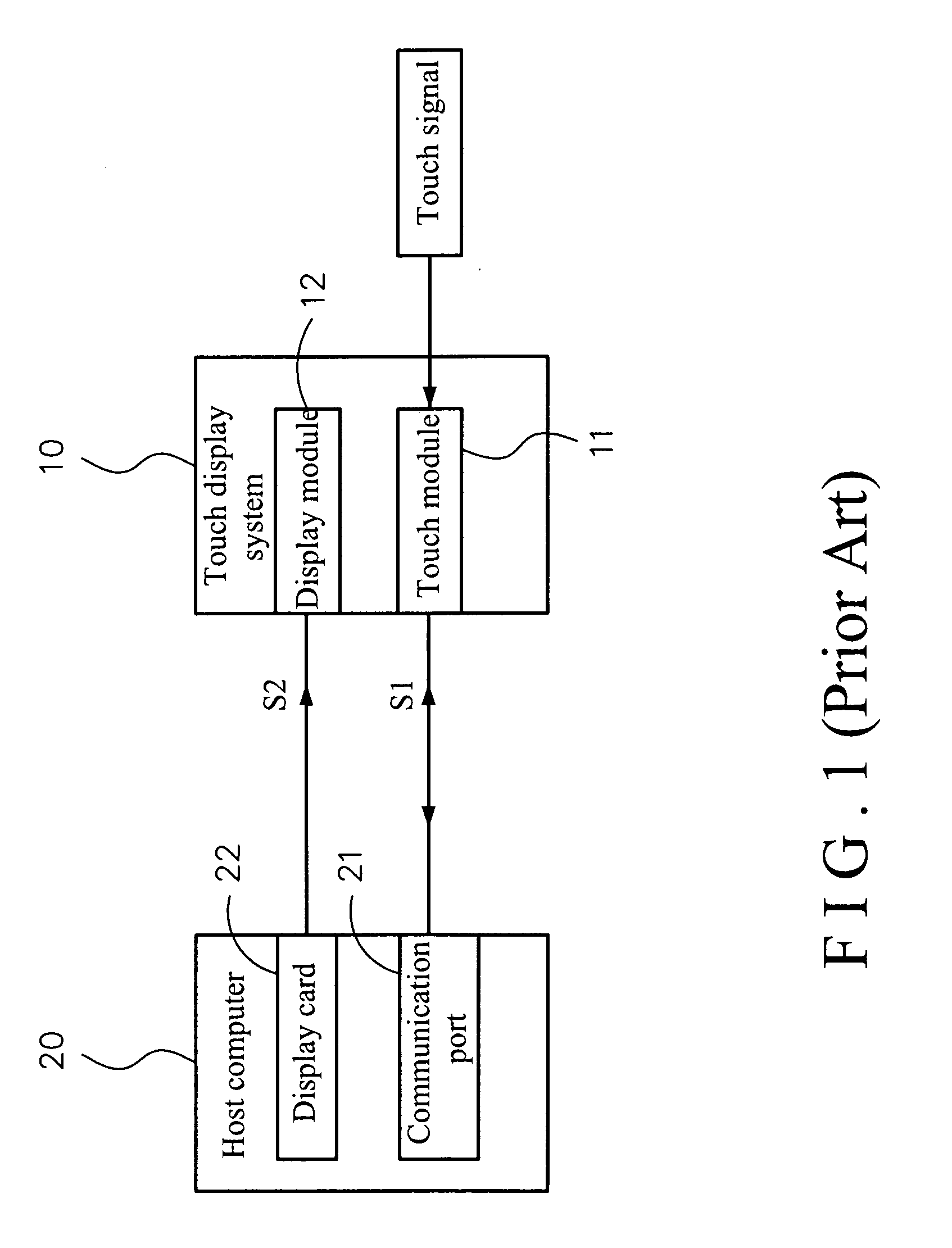
BACKGROUND OF THE INVENTION[0001](1) Field of the Invention[0002]The present invention relates to a touch display system and control method thereof, and more particularly relates to a touch display system and control method thereof.[0003](2) Description of the Related Art[0004]Refer to FIG. 1 for a functional diagram of a conventional touch display system 10. The touch display system 10 includes a touch module 11 and a display module 12, both connected to a host computer 20. The host computer 20 includes a communication port 21 and a display card 22. The communication port 21 is such as Universal Serial Bus (USB) or RS 232 serial port. The display card 22 is such as Video Graphics Array (VGA), Digital Visual Interface (DVI) or Display Data Channel Command Interface (DDC / CI).[0005]The host computer 20 sends a start signal along a path S1 from the communication port 21 to the touch module 11 to start the touch module 11. After receiving a touch signal, the touch module 11 sends the to...

Claims


Application Information

Patent Timeline
IPC IPC(8): G06F3/01G06F1/32G06F3/048
CPCG09G2354/00G06F3/0488
Inventor CHANG, PO-CHUN
Owner CORETRONIC
Why Eureka
Try Eureka