System and method for performing automated testing of protective relay equipment

a technology of relay equipment and automated testing, applied in the direction of electrical testing, measurement devices, instruments, etc., can solve the problems of failure of output to assert, multiple errors can be detected, and many of the tests can only be carried ou

Inactive Publication Date: 2010-09-23
MANTA TEST SYST
View PDF5 Cites 18 Cited by
  • Summary
  • Abstract
  • Description
  • Claims
  • Application Information

AI Technical Summary

Benefits of technology

[0018]In yet another aspect, there is provided a computer readable storage medium comprising computer executable instructions for enabling the performance of protective relay testing, the computer readable storage medium comprising instructions for: obtaining a test set definition indicative of operations to be performed by a test set for the protective relay testing; obtaining a test case description indicative of the nature of the test to be performed; generating a command file comprising a test case description by converting the test case description from an internal format to a format understood by the test set using the test set definition; and outputting the command file to enable the command file to be provided to the test set.

Problems solved by technology

In that way, various errors can be detected, including failure of an output to assert, spurious assertion of the output, early assertion of the output, or late assertion of the output.
The routine testing schedule can require test technicians to execute a large number of tests at each substation, and many of the tests can only be carried out while the substation, or part of it, is off-line.
In some cases an approved outage planned a year in advance is cancelled at the last moment due to unexpected demand on the power system due to weather or unanticipated system conditions.
Moreover, the PC is typically a portable unit such as a laptop and may have limited computing power or limited access to corporate database servers and other resources.

Method used


Image

  • System and method for performing automated testing of protective relay equipment
  • System and method for performing automated testing of protective relay equipment
  • System and method for performing automated testing of protective relay equipment

Examples


Embodiment Construction

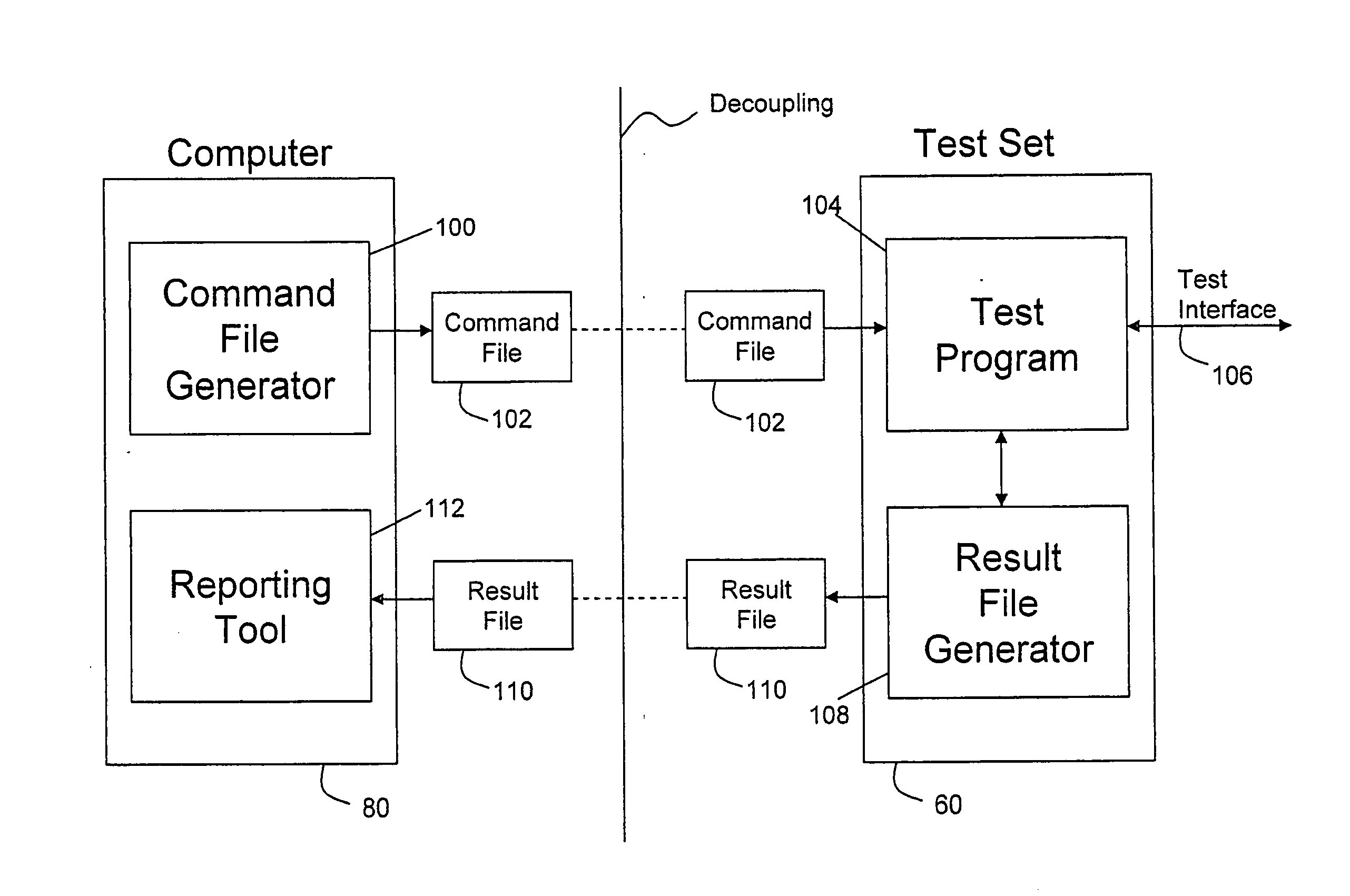
[0037]It has been recognized that to avoid the need to tether a computer to a test set in order to run a test sequence and obtain result data, a decoupling can be performed by generating command files that can be placed in storage media or provided to the test set separately rather than sending timed commands directly from the computer to the test set. Similarly, a result file generator on the test set can obtain test results and generate a result file that can be placed in such storage media or transported separately to be used by a reporting tool on the computer in the normal fashion. It has been found that various ways of decoupling are possible, using any suitable transport scheme including physical and electronic, both wired and wireless.

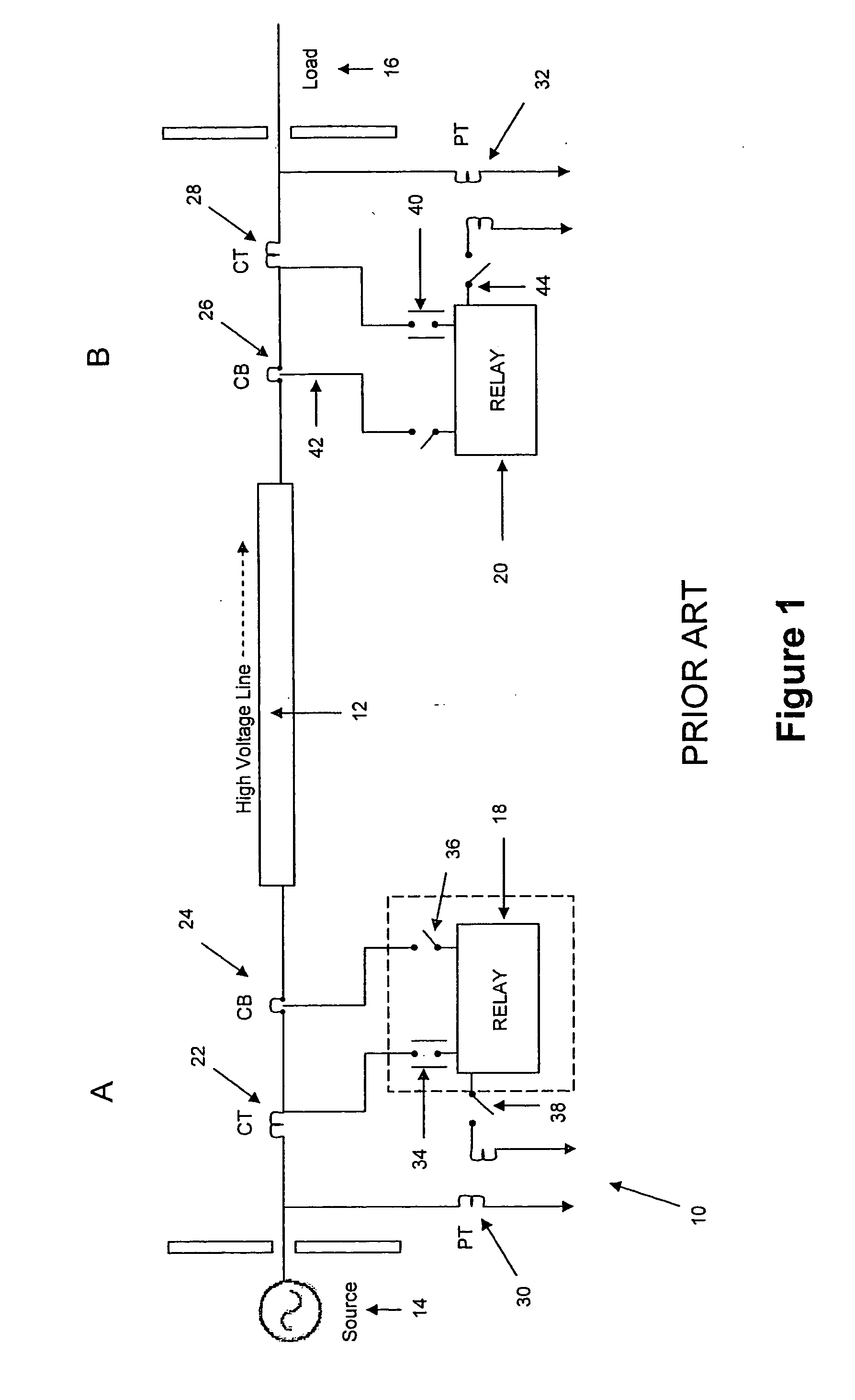
[0038]Referring first to FIG. 1, an exemplary protective relay testing arrangement as is known in the prior art is generally denoted by numeral 10. In this example, a high voltage transmission line 12 between a power source 14 and a load 16 is ...


PUM


Abstract

A system and method are provided that avoid the need to tether a computer to a test set in order to run a test sequence on a protective relay and obtain result data. A decoupling can be performed by generating command files that can be placed in storage media or provided to the test set separately rather than sending timed commands directly from the computer to the test set. Similarly, a result file generator on the test set can obtain test results and generate a result file that can be placed in such storage media or transported separately to be used by a reporting tool on the computer in the normal fashion. It has been found that various ways of decoupling are possible, using any suitable transport scheme including physical and electronic, both wired and wireless.

Description

[0001]This application claims priority from U.S. Provisional Patent Application No. 61 / 202,305 filed on Feb. 17, 2009, the contents of which are incorporated herein by reference.FIELD OF THE INVENTION[0002]The present invention relates generally to electrical power system protection and control, and has particular utility in performing automated testing of protective relay equipment.DESCRIPTION OF THE PRIOR ART[0003]Electrical power systems typically make use of protection systems for increasing the reliability of the power system's infrastructure. A common component of such protection systems includes a protective relay, which, in general, monitors the current and voltage at a particular node in the power system, and, if a fault is detected, provides one or more trip signals to trip a circuit breaker in order to isolate a portion of the system. Often, more than one protective relay is needed to completely isolate a portion of the system, which may be a 3-phase power line, a generat...

Claims


Application Information

Patent Timeline
Patent Type & Authority Applications(United States)
IPC IPC(8): G06F11/07
CPCG01R31/3274
Inventor GILBERTSON, SCOTTWERSTIUK, CHRISTOPHER DOUGLASCOOPER, JOHN SCOTT
Owner MANTA TEST SYST
Why Eureka
Try Eureka