Surface traversing apparatus and method

Active Publication Date: 2005-04-07
INT CLIMBING MACHINES
View PDF24 Cites 32 Cited by
  • Summary
  • Abstract
  • Description
  • Claims
  • Application Information

AI Technical Summary

Benefits of technology

[0021] In another embodiment, robotic arms are mounted to the device, thereby enabling the performance of an endless array of remote-controlled tasks such as, but not limited to, welding, cutting, sawing, lifting, performing repairs, etc.
[0022] The rolling and locomoting seal used in aspects of this invention reduces the amount of energy required to move the device along surfaces. Overcoming the friction from static type seals of past inventions requires large motors and significant force, adding weight and energy consumption. Energy consumption and motor sizes can thereby be reduced with this invention.
[0023] The merits of this invention dramat

Problems solved by technology

This approach to surface traversal is slow, erratic, and does not lend itself to operations where smooth, continuous travel is needed (such as cleaning, coating removal, decontamination surveys, etc.).
Further, it has limitations in terms of surface obstacles that it can encounter and circumvent.
On rough or uneven surfaces, a large percentage of the suction cups are unable to make firm contact, thus the devices lose adhesion.
Such a device would not work well on spalled concrete, where the surface is very uneven, or on many bridge structures where the surfaces include many plates bolted together.
The large bolts and the unevenness of the plates render the suction cup adhering device ineffectual at negotiating these surfaces.
The valving on this type of device is typically very complex, since the vacuum is only applied to the cups that are firmly secured and not applied to the cups that are not firmly secured to the surface.
Otherwise, too much vacuum loss will occur.
This has dramatically limited the use of this type of design to applications justifying a very complex and costly device and/or where relatively flat, smooth surfaces exist, such as commercial aircraft skins.
While the vacuum force in the large chamber a

Method used


Image

  • Surface traversing apparatus and method
  • Surface traversing apparatus and method
  • Surface traversing apparatus and method

Examples


Embodiment Construction

[0044] The presently preferred and alternative embodiments of the invention, including the best mode for practicing the invention known to the inventor at this time, are now described in detail in connection with the accompanying drawings. The terms “device” and “apparatus” are used interchangeably in varying instances and contexts herein to refer to the surface traversing apparatus according to various embodiments of the invention.

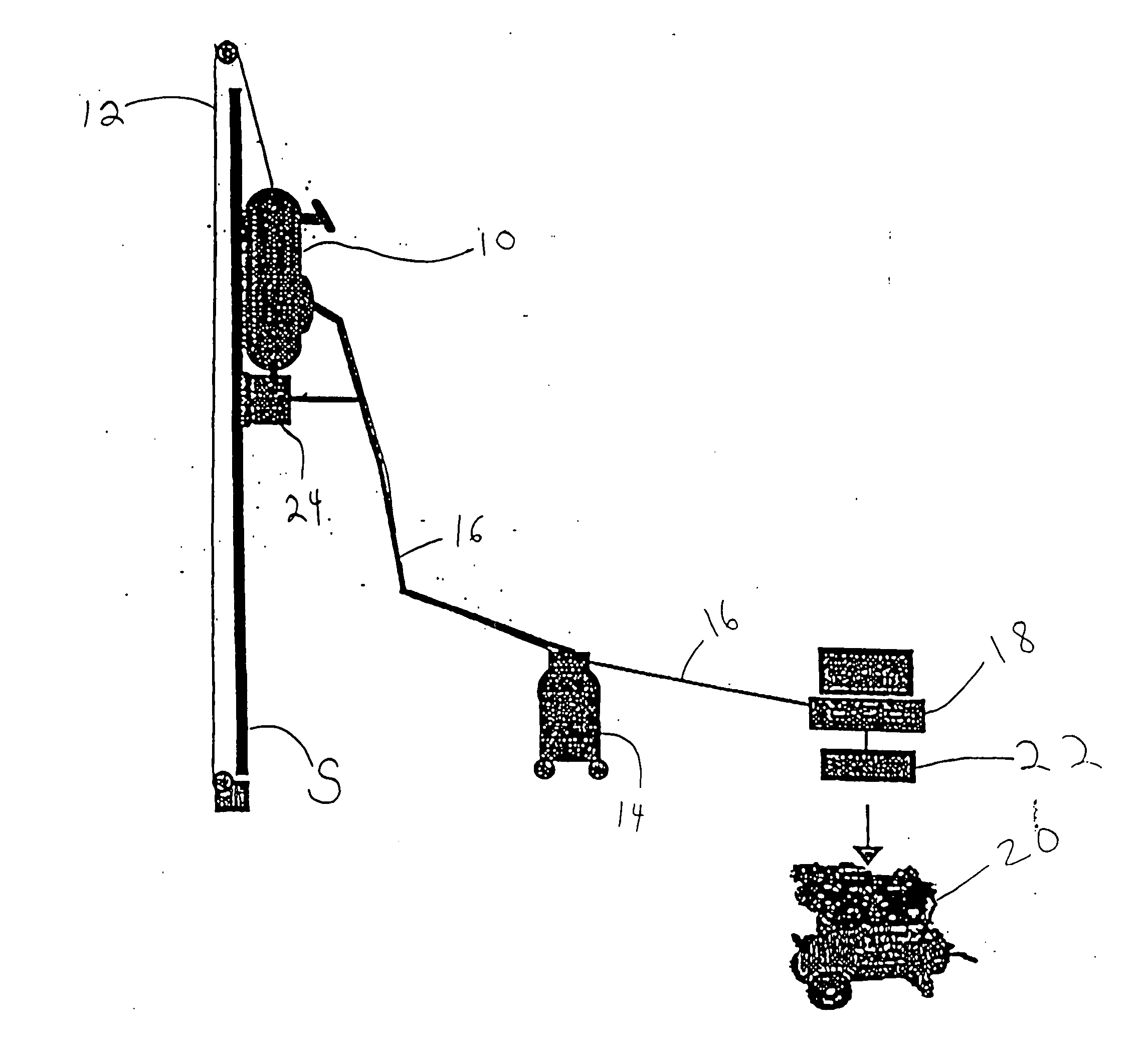
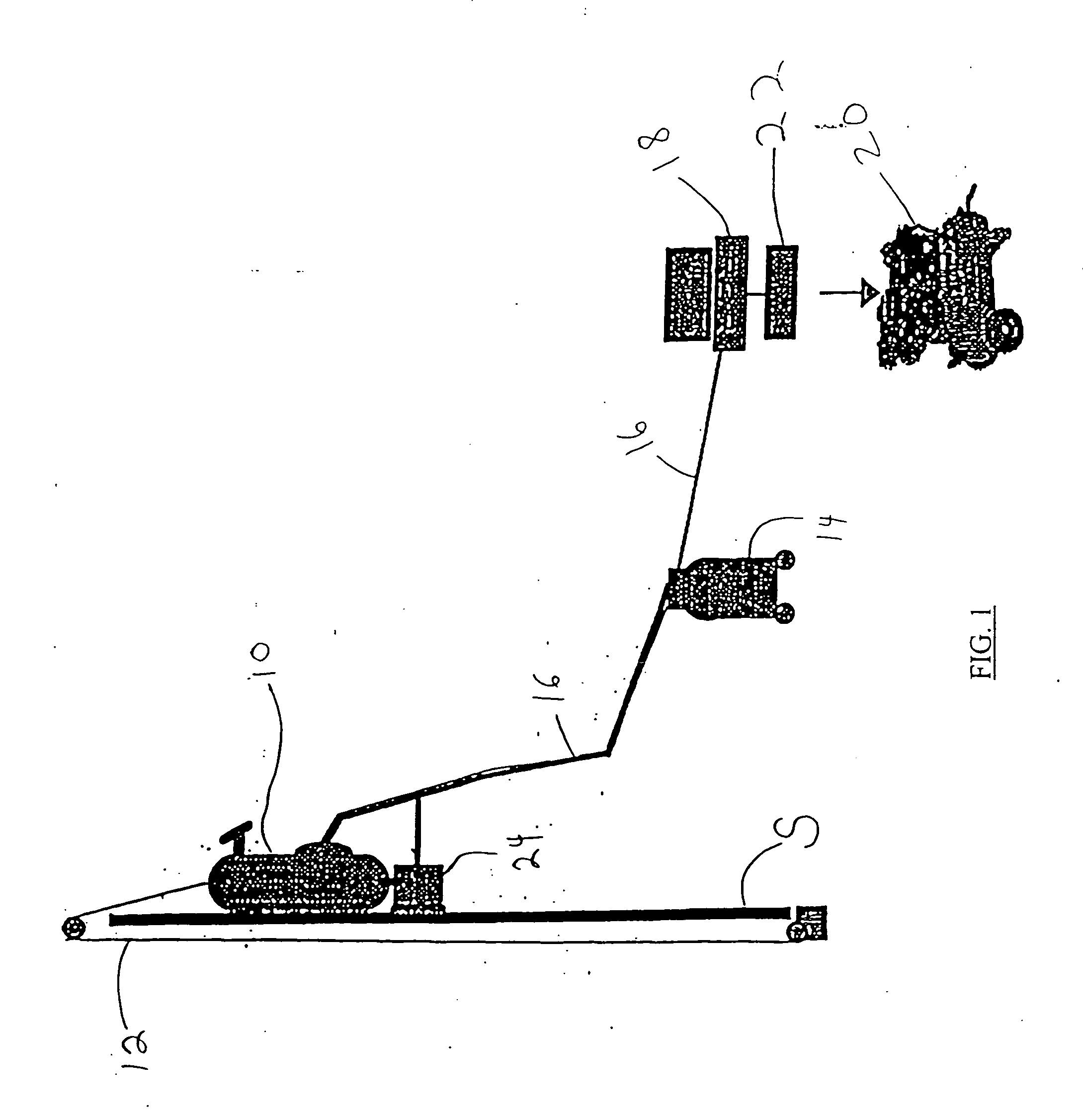
[0045] Referring to FIG. 1, an embodiment of a surface traversing apparatus 10 is shown adhering to an exemplary vertical surface S. FIG. 1 is a schematic diagram depicting an embodiment of the apparatus 10 for the purpose of showing the apparatus 10 operating in a given exemplary environment. The device 10 can operate in various environments including, but not limited to underwater, radioactive, toxic, hazardous, varying altitudinal as well as conventional manufacturing and construction environments.

[0046] Further, various auxiliary and support compone...


PUM

PropertyMeasurementUnit
Pressureaaaaaaaaaa
Poweraaaaaaaaaa
Flexibilityaaaaaaaaaa

Abstract

The invention concerns a surface traversing apparatus that includes a frame, a seal having a seal perimeter that is mounted to the frame, and a drive configured to move the apparatus relative to the surface. The seal perimeter is adapted substantially for rolling contact with the surface to be traversed. The device is capable of suction adhering and moving along horizontal, vertical, inverted surfaces and the like, and overcoming obstacles or surface irregularities while maintaining suction adhesion to the surface. The device can be propelled along the surface with a locomoting rolling seal assembly, which provides both a seal to affect the vacuum adhesion and the locomotion to drive the device across the surface.

Description

FIELD OF THE INVENTION [0001] The present invention relates generally to the field of remote controlled devices and robotics. More specifically, the present invention relates to an apparatus for and methods of traversing while adhering to a surface. BACKGROUND OF THE INVENTION [0002] Remote controlled devices and robots are in use in various aspects of science and industry, including automotive, construction, exploratory, salvage, painting, surface preparation, diagnostic and environmental cleanup industries. Increasingly, there are instances requiring remote controlled devices capable of surface traversing or climbing. Innovation in this field would be beneficial for elevated height surface climbing or when surfaces need to be decontaminated, cleaned, or coated with devices that reduce exposure of humans to contamination and to potentially hazardous elevated height working conditions. This has led to the development of a sub-field of remote controlled devices and robotics relating ...

Claims


Application Information

Patent Timeline
IPC IPC(8): B62D57/024B62D61/04B62D61/10B63B59/10E04G23/00
CPCB62D49/0635B62D55/02B62D55/06B62D55/265B62D57/00Y10T156/1788B62D61/04B62D61/10B63B59/10E04G23/002B62D57/024
Inventor MAGGIO, SAMUEL J.
Owner INT CLIMBING MACHINES
Why Eureka
Try Eureka