
Structural shape for wind tower members

Inactive Publication Date: 2010-09-30
GE WIND ENERGY
View PDF100 Cites 22 Cited by
  • Summary
  • Abstract
  • Description
  • Claims
  • Application Information

AI Technical Summary

Benefits of technology

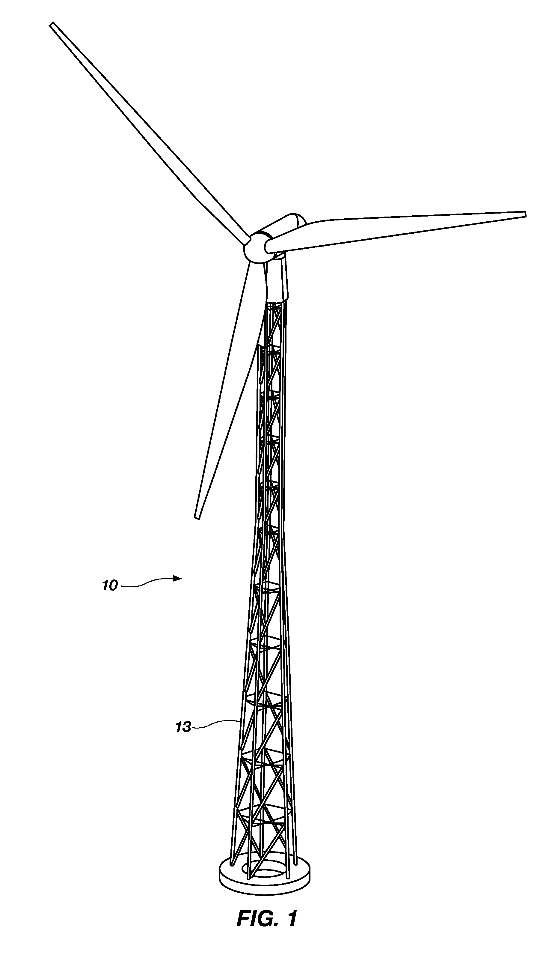
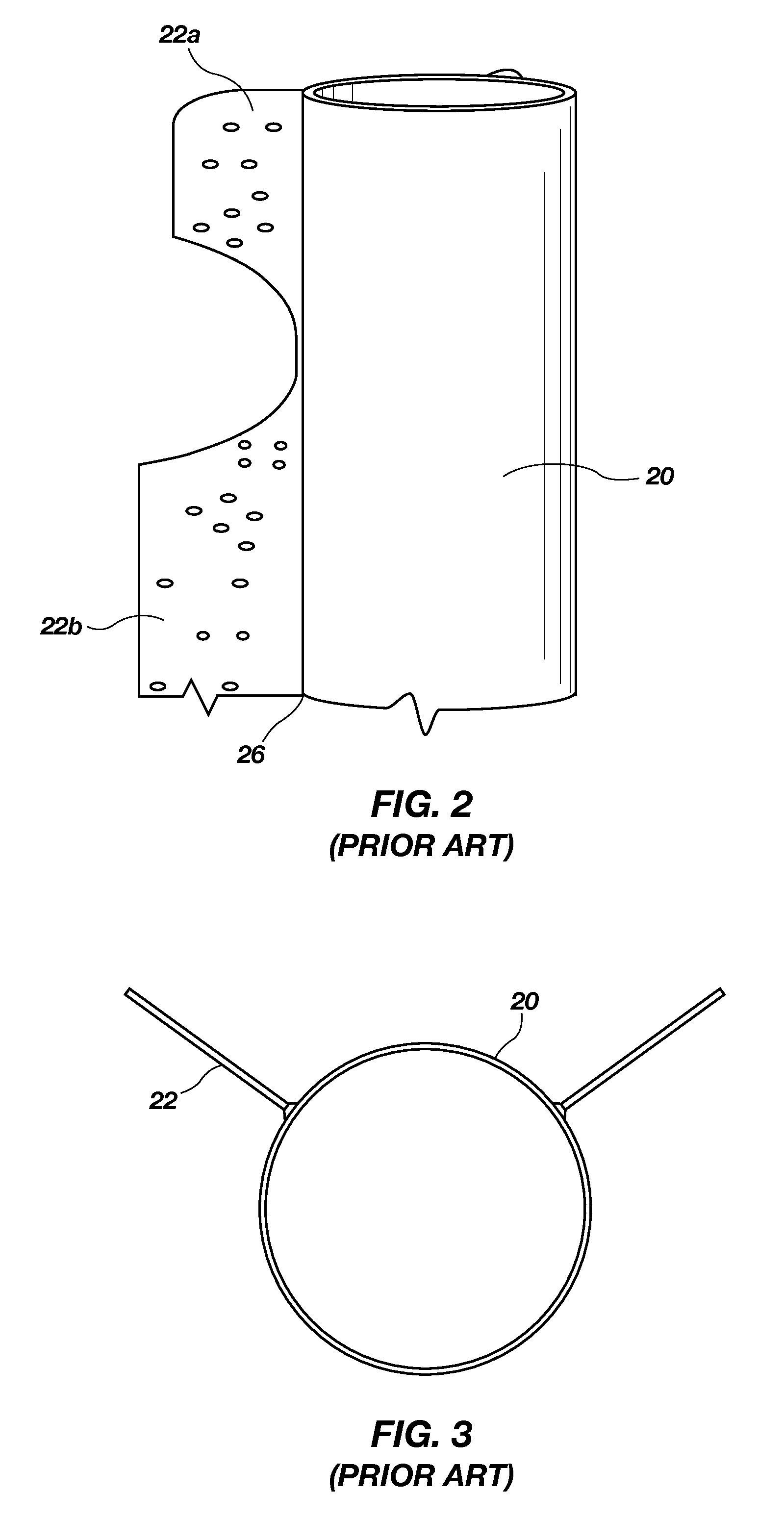
[0012]The leg design in existing towers is tubular. Gussets are welded to the tubular pipe and the pipes are connected in the gussets through cross bracing. The disadvantage of this design is that the gussets must be welded to the tower leg and this might cause fatigue problems in the leg. FIG. 2 shows that the gussets are not continuous along the length of the pipe and there is a gap between them because the gussets were designed just to support the cross bracing and they do not transfer the axial loads and the bending loads therethrough. So it is the pipe which supports all the axial and bending loads. This increases the overall weight of the tower. So there is a need to eliminate the welds in the gussets and at the same time bring down the weight of the tower. This has given rise to this disclosure as further discussed below.
[0013]The next generation cross section was designed keeping in mind that the limitations in the existing tower cross sections have to be overcome. The next generation leg may be designed in such a way that flanges from the structure act as support for cross bracing and also assists in transferring the axial and the bending loads. In other words, this desirable feature eliminates the need for gussets to be welded to the tower leg. One desirable attribute of the present disclosure is to eliminate welded joints in the tower leg. As the flanges of the tower serve as load path for axial and bending loads, the cross sectional area can be reduced which in turn lowers the mass of the tower.

Problems solved by technology

The disadvantage of this design is that the gussets must be welded to the tower leg and this might cause fatigue problems in the leg. FIG. 2 shows that the gussets are not continuous along the length of the pipe and there is a gap between them because the gussets were designed just to support the cross bracing and they do not transfer the axial loads and the bending loads therethrough.
This increases the overall weight of the tower.

Method used


Image

  • Structural shape for wind tower members
  • Structural shape for wind tower members
  • Structural shape for wind tower members

Examples


Embodiment Construction

[0120]For the purposes of promoting an understanding of the principles in accordance with the disclosure, reference will now be made to the embodiments illustrated in the drawings and specific language will be used to describe the same. It will nevertheless be understood that no limitation of the scope of the disclosure is thereby intended. Any alterations and further modifications of the inventive features illustrated herein, and any additional applications of the principles of the disclosure as illustrated herein, which would normally occur to one skilled in the relevant art and having possession of this disclosure, are to be considered within the scope of the disclosure claimed.

[0121]In describing and claiming the present disclosure, the following terminology will be used in accordance with the definitions set out below. As used herein, the terms “comprising,”“including,”“containing,”“characterized by,” and grammatical equivalents thereof are inclusive or open-ended terms that do...


PUM

PropertyMeasurementUnit
Fractionaaaaaaaaaa
Fractionaaaaaaaaaa
Fractionaaaaaaaaaa

Abstract

One of the major structural components in a space frame tower is the tower leg. A novel and nonobvious tower leg structure is provided which provides significant advantages and benefits over previously available structures.

Description

CROSS-REFERENCE TO RELATED APPLICATIONS[0001]This application claims the benefit of U.S. Provisional Application No. 61 / 122,593, filed Dec. 15, 2008, which is hereby incorporated by reference herein in its entirety, including but not limited to those portions that specifically appear hereinafter, the incorporation by reference being made with the following exception: In the event that any portion of the above-referenced provisional application is inconsistent with this application, this application supercedes said above-referenced provisional application.[0002]This application also claims the benefit of U.S. Provisional Application No. 61 / 163,857, filed Mar. 26, 2009, which is hereby incorporated by reference herein in its entirety, including but not limited to those portions that specifically appear hereinafter, the incorporation by reference being made with the following exception: In the event that any portion of the above-referenced provisional application is inconsistent with t...

Claims


Application Information

Patent Timeline
IPC IPC(8): E04C3/32B23P11/00
CPCE04H12/10F03D11/04Y10T29/49895Y02E10/728F05B2240/9121F03D13/20Y02E10/72E04H12/085E04H12/24E04H12/34
Inventor OLIPHANT, DAVIDANDERSEN, TODD
Owner GE WIND ENERGY
Learn More