
Exhaust gas-treating device

a gas-treatment device and exhaust gas technology, which is applied in the direction of mechanical equipment, machines/engines, separation processes, etc., can solve the problems of reducing the storage capacity of the particle filter, increasing the flow resistance, and a comparatively great manufacturing effort, and achieves the effect of simple handling of changing the particle filter

Active Publication Date: 2010-09-30
EBERSPACHER EXHAUST TECH GMBH & CO +1
View PDF8 Cites 24 Cited by
  • Summary
  • Abstract
  • Description
  • Claims
  • Application Information

AI Technical Summary

Benefits of technology

[0004]The present invention pertains to the object of providing an improved embodiment for an exhaust gas-treating device of the type mentioned in the introduction, which is characterized especially by simple handling for changing the particle filter.
[0006]The mode of construction being proposed creates sufficient access to the particle filter for maintenance purposes without the housing itself having to be opened for this. The detachable attachment of such a deflecting housing is comparatively simple and inexpensive.
[0007]Corresponding to an advantageous embodiment, an outlet-side end section of the particle filter, which faces the deflecting housing, may be designed such that it can be integrated in the fastening means, which is provided for the detachable fastening of the inlet of the deflecting housing at the outlet end of the mounting tube, such that axial fixation of the particle filter at the mounting tube or at the inlet of the deflecting housing is achieved hereby. In other words, the fastening means, which is used to fasten the deflecting housing to the housing of the exhaust gas-treating device, assumes a dual function, because the particle filter inserted into the mounting tube is axially fixed with it at the same time. This facilitates the mounting and removal or replacement of the particle filter, because no separate additional fastening means has to be actuated, which could be intended for the separate fixation of the particle filter.
[0008]Corresponding to another advantageous embodiment, an inlet-side end section of the particle filter, which faces away from the deflecting housing, can be radially supported at the mounting tube in an axially displaceable manner. The particle filter can perform relative motions as a result in relation to the mounting tube in the area of its inlet-side end section. This is of increased significance especially in respect to thermal expansion effects. The axially displaceable supporting leads to a movable bearing of the particle filter in or at the mounting tube in the area of the inlet-side end section, while the axial fixation provided at the inlet-side end section of the particle filter quasi forms a fixed bearing between the particle filter and the mounting tube. This combination leads to secure and stable supporting or fixation of the position of the particle filter in the mounting tube and is, moreover, extensively free from thermal stresses.

Problems solved by technology

Since particles that cannot be burned off are also deposited in the particle filter, the particle filter gradually becomes clogged despite regenerations, which reduces the storage capacity of the particle filter and increases the flow resistance thereof.
It is undesirable in this connection to replace the entire exhaust gas-treating device.
For example, flanged fastenings are conceivable, but this means increased weight as well as a comparatively great manufacturing effort.
Plug-in connections are quasi ruled out because these can be detached with very great difficulty only or not at all any more after a long connection time.

Method used


Image

  • Exhaust gas-treating device
  • Exhaust gas-treating device
  • Exhaust gas-treating device

Examples


Embodiment Construction

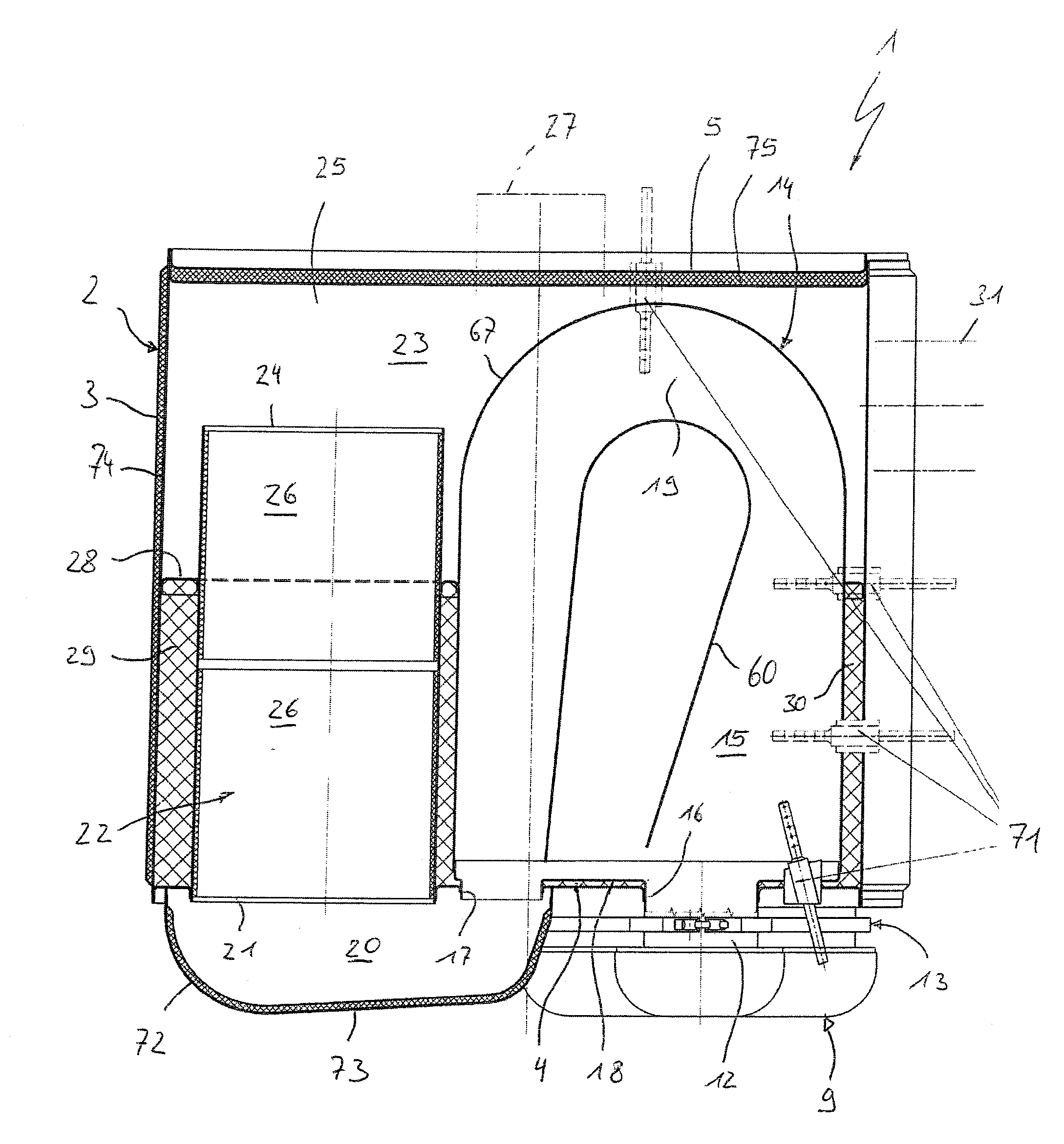
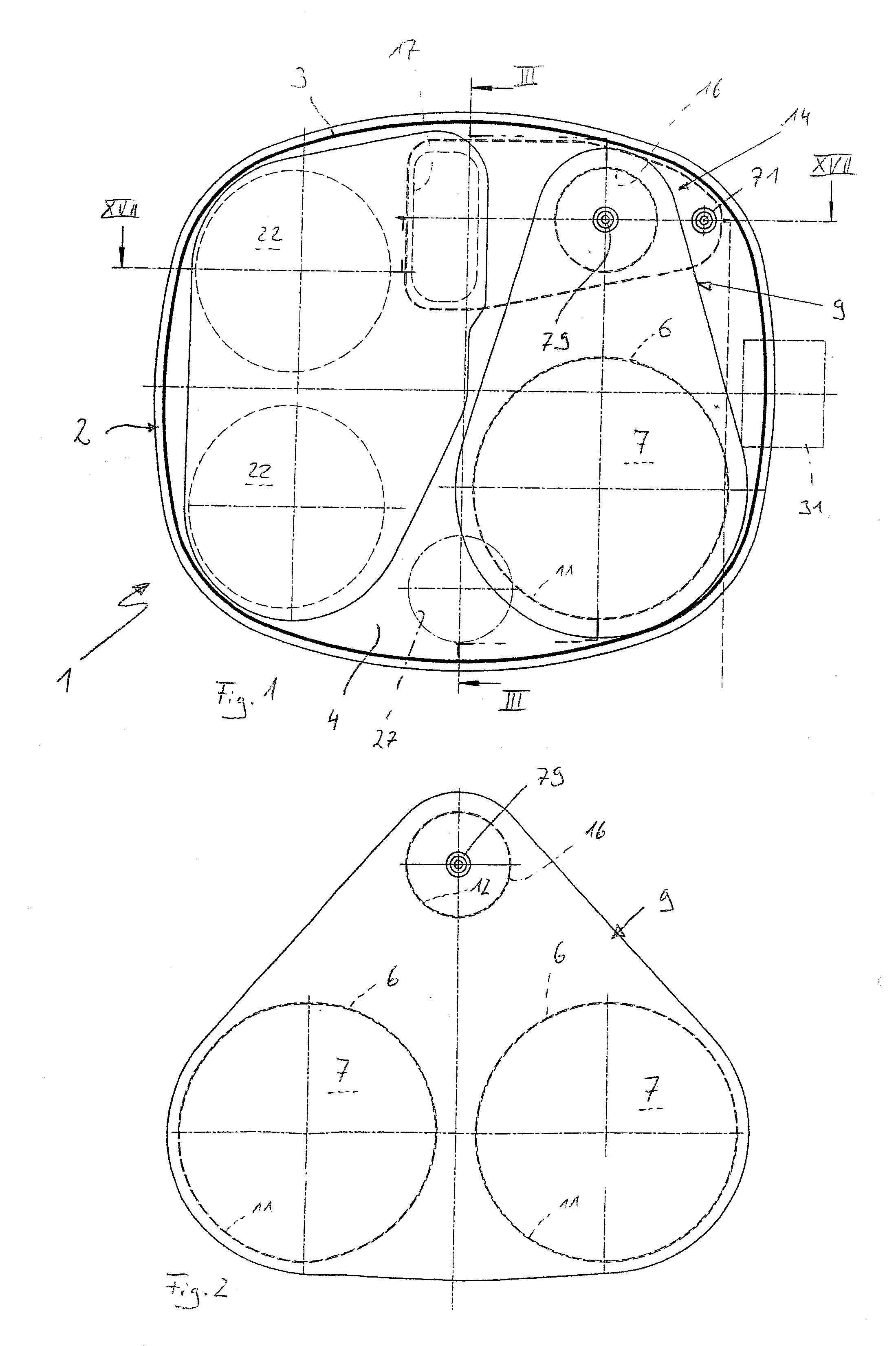
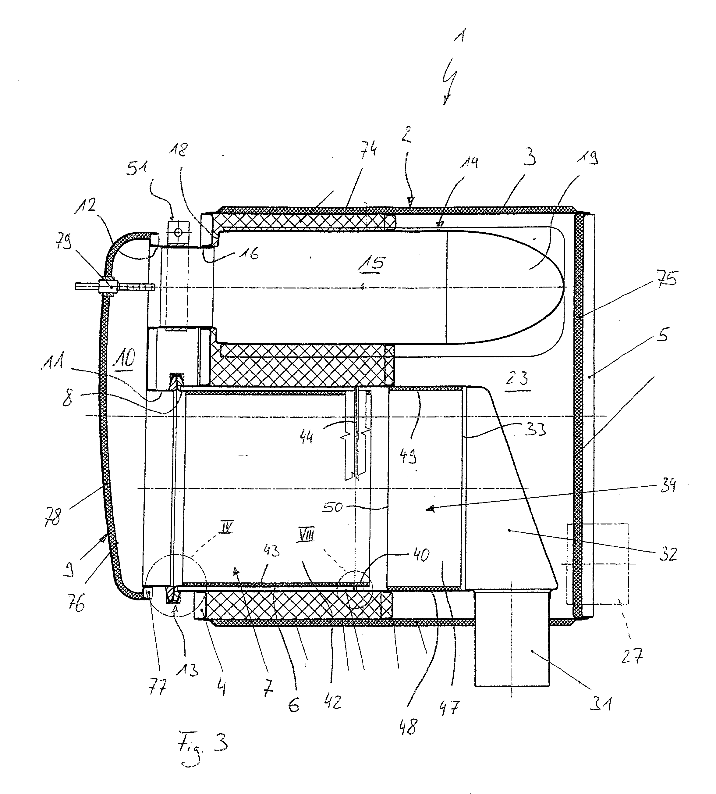
[0043]Referring to the drawings in particular, corresponding to FIG. 1, an exhaust gas-treating device 1, which is intended for use in an exhaust system of an internal combustion engine, especially of a motor vehicle, may have a housing, which has a jacket 3 extending laterally circumferentially, as well as two end-side bottoms or end bottoms 4, 5, of which only one or the first end bottom 4 faces the viewer in FIG. 1. The other or second end bottom 5 is arranged at the end of the housing 2 located away from the first end bottom 4.

[0044]Corresponding to FIGS. 1-3, the exhaust gas-treating device 1 is preferably equipped with at least one mounting tube 6. Precisely one such mounting tube 6 is provided in the embodiment shown in FIGS. 1 and 3. FIG. 2 shows, purely as an example, an embodiment with two such mounting tubes 6. The respective mounting tube 6 passes axially through the first end bottom 4. Furthermore, the respective mounting tube 6 accommodates a particle filter 7. The res...


PUM

PropertyMeasurementUnit
Angleaaaaaaaaaa
Angleaaaaaaaaaa
Flow rateaaaaaaaaaa

Abstract

An exhaust gas-treating device (1) for an exhaust system of an internal combustion engine, especially of a motor vehicle, has a housing (2), which has a jacket (3) extending circumferentially on the side and two end-side end bottoms (4, 5). Maintenance is simplified with at least one mounting tube (6), which passes through one or the first end bottom (4) and into the outlet end (8) of which a particle filter (7) is plugged axially from the outside, with a deflecting housing (9). The deflecting housing (9) contains a deflecting chamber (10), and has at least one inlet (11) communicating with the deflecting chamber (10) and at least one outlet (12) communicating with the deflecting chamber (10). A fastening device (13) is provided for detachably fastening the respective inlet (11) at the respective outlet end (8) of the mounting tube (6).

Description

CROSS REFERENCE TO RELATED APPLICATIONS[0001]This application claims the benefit of priority under 35 U.S.C. §119 of German Patent Application DE 10 2009 014 435.8 filed Mar. 26, 2009, the entire contents of which are incorporated herein by reference.FIELD OF THE INVENTION[0002]The present invention pertains to an exhaust gas-treating device for an exhaust system of an internal combustion engine, especially of a motor vehicle.BACKGROUND OF THE INVENTION[0003]Such an exhaust gas-treating device may contain at least one particle filter in order to filter out particles carried in the exhaust gas, especially soot. The particles filtered out are deposited in a particle filter element of the particle filter. The storage capacity of the particle filter decreases with increasing load, and the flow resistance of the particle filter increases at the same time. Regenerations are correspondingly carried out, during which the particle load is burned off. Since particles that cannot be burned off...

Claims


Application Information

Patent Timeline
IPC IPC(8): F01N3/035F01N3/02F01N1/00F01N3/10
CPCF01N1/084F01N3/0211F01N3/2066F01N3/28F01N13/1838F01N2450/30B01D46/0005Y02T10/24F01N13/0097F01N3/08F01N3/2882F01N3/2892F01N2470/22Y10T29/4973Y02A50/20Y02T10/12
Inventor WERNI, MARCUSLEHNEN, RAINER
Owner EBERSPACHER EXHAUST TECH GMBH & CO
Learn More