Shaping tool having a rotatable base member

a technology of rotatable base and tool, which is applied in the direction of single-unit apparatus, metal rolling arrangement, other domestic objects, etc., can solve the problems of non-gastight end contour, defect, etc., and achieve the effect of reliable operation

Active Publication Date: 2010-09-30
BOEHRINGER INGELHEIM INT GMBH
View PDF3 Cites 24 Cited by
  • Summary
  • Abstract
  • Description
  • Claims
  • Application Information

AI Technical Summary

Benefits of technology

[0003]The problem that the invention sets out to solve is to provide a s...

Problems solved by technology

In the event of incorrect axial positioning, the pressing member would act upon the lev...

Method used


Image

  • Shaping tool having a rotatable base member
  • Shaping tool having a rotatable base member
  • Shaping tool having a rotatable base member

Examples


Embodiment Construction

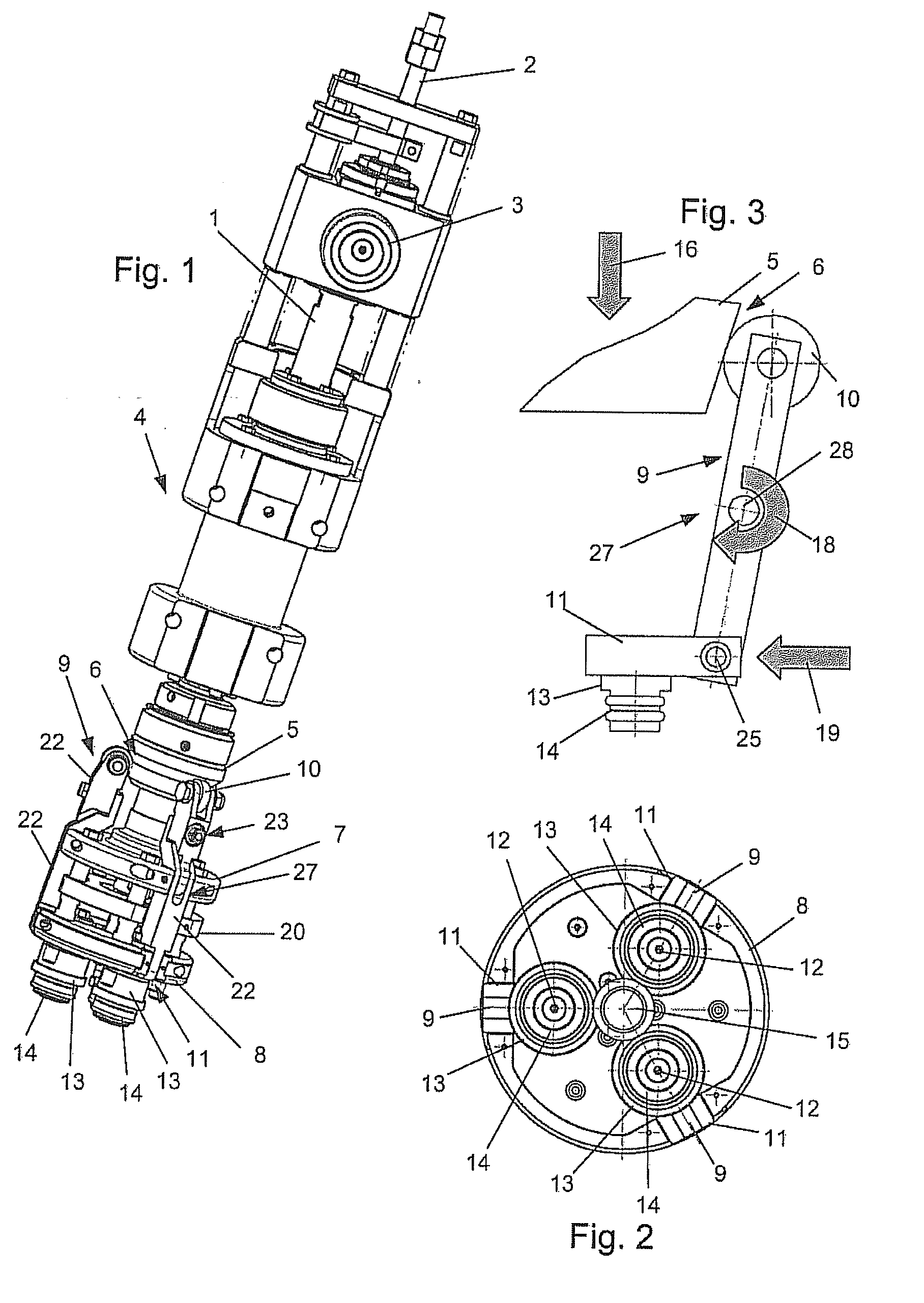
[0025]The shaping tool comprises a rod 2 mounted in a hollow shaft 1 and connected to a rotary drive (not shown). An axial up and down movement of the shaping tool is controlled by means of a radially mounted cam roller 3 on the tool side, which cooperates with a cam control. In a housing 4 are various mounting, coupling and spring elements.

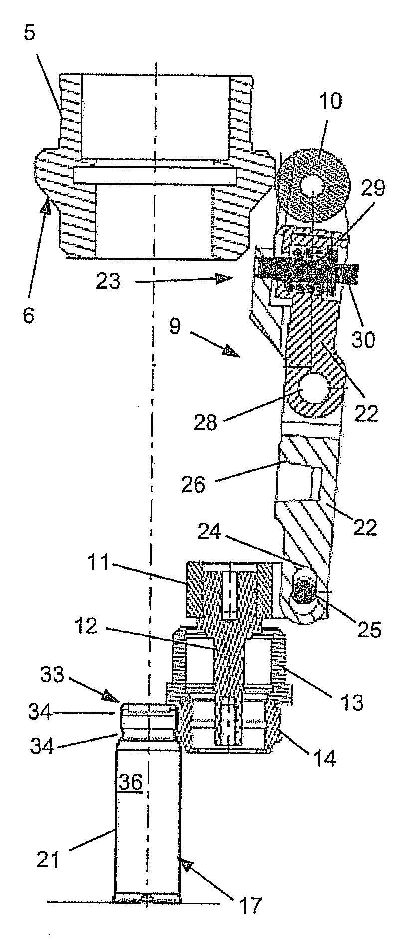
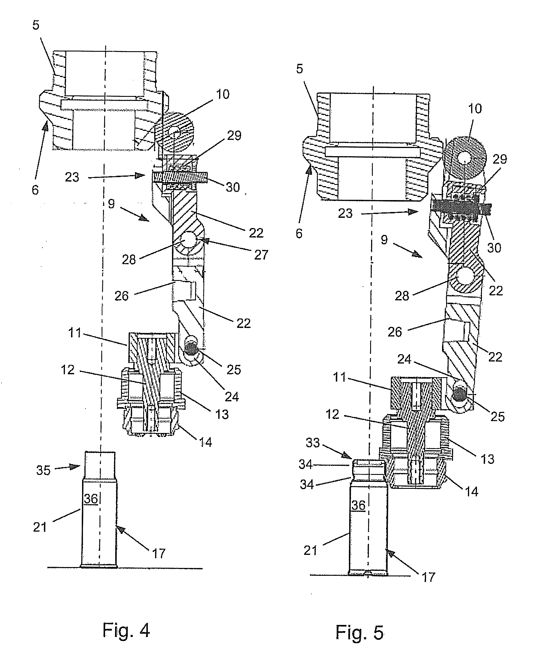
[0026]Underneath the housing 4 is secured a pressing member 5 with a conical region 6 and underneath the pressing member 5 are a carrier member 7 and a guide portion 8, while pivotably mounted in the carrier member 7 are three levers 9 which comprise, at one end, rollers 10 cooperating with the pressing member 5, while the opposite ends from the rollers 10 act upon slides 11 mounted in the guide portion 8. Each of the slides 11 has a bending roller 13 and a shaping roller 14 on a spindle 12.

[0027]By means of the pivotable levers 9, the bending rollers 13 can be moved out of a position that defines a maximum working aperture for the tool into a po...


PUM


Abstract

A shaping tool as depicted in exemplary FIG. 3 comprising a rotatable base member having at least one profiled bending roller (13) which is mounted on a circular track and is rotatable about a rotation axis. The bending roller (13) arranged on a radially movable slide (11) is movable from a position defining a maximum working aperture for the tool, by means of a spring-loaded lever (9) which has an axial configuration, into a position defining a minimum working aperture for the tool.

Description

BACKGROUND OF THE INVENTION[0001]For administering inhalable pharmaceutical formulations of active substances, the patient uses hand-held, manually operated inhalers in which the pharmaceutical active substance formulation is contained in an inhaler cartridge. The inhaler cartridge consists of an external aluminium cartridge and a plastic container inserted therein, the plastic container being produced by co-extrusion and comprising a rigid outer container and a flexible inner pouch disposed inside it. In order to create a pressure equalisation opening between the inner pouch and the outer container, an opening is formed in the relatively rigid outer container by the so-called cut-crack-open process, for example. The plastic container is filled with the pharmaceutical active substance formulation and sealed, and inserted into the aluminium cartridge during the manufacturing process to form the inhaler cartridge. In a subsequent step, a deformed wall region is formed in the aluminium...

Claims


Application Information

Patent Timeline
IPC IPC(8): B21D19/06A61M15/00
CPCA61M11/00A61M15/009B05B11/00B21D15/06B21D17/04B21D51/54B21D51/24B21D51/2615B21D51/263B21D51/2638B21D39/04B05B11/1091
Inventor SPREITZER, JOERGHUEBNER, MICHAELMATHE, GERALD
Owner BOEHRINGER INGELHEIM INT GMBH
Why Eureka
Try Eureka