Solar cell, solar cell module and solar cell system

a solar cell and module technology, applied in the field of solar cells, can solve the problems of low production yield of solar cells, high cost, easy cracking of substrates, etc., and achieve the effect of improving production yield

Inactive Publication Date: 2010-09-30
PANASONIC INTELLECTUAL PROPERTY MANAGEMENT CO LTD
View PDF8 Cites 81 Cited by
  • Summary
  • Abstract
  • Description
  • Claims
  • Application Information

AI Technical Summary

Benefits of technology

[0011]However, the conventional wide bus bar electrodes require the use of a large amount of electrode material, and accordingly often require high cost. To avoid this, it is worthwhile to consider reducing the width of the bus bar electrodes.
[0012]Even in a case where narrow bus bar electrodes are used, however, there is a problem that cracks in the substrate occurs easily, thus lowering the production yield of solar cells. The problem occurs due to a configuration in which the bus bar electrodes forming the front surface electrode have the same shape as the bus bar electrodes forming the rear surface electrode, when viewed in a perpendicular direction from the front surface of the solar cell (the semiconductor substrate forming the cell). Here, a large difference in the thermal expansion coefficient between the substrate, the front surface electrode, and the rear surface electrode generates stresses on the front surface side and the rear surface side due to temperature variations during the manufacturing process or the like. In the above configuration, the stresses are added to the substrate in substantially the same direction, and hence cause the substrate to crack easily.

Problems solved by technology

However, the conventional wide bus bar electrodes require the use of a large amount of electrode material, and accordingly often require high cost.
Even in a case where narrow bus bar electrodes are used, however, there is a problem that cracks in the substrate occurs easily, thus lowering the production yield of solar cells.
The problem occurs due to a configuration in which the bus bar electrodes forming the front surface electrode have the same shape as the bus bar electrodes forming the rear surface electrode, when viewed in a perpendicular direction from the front surface of the solar cell (the semiconductor substrate forming the cell).
In the above configuration, the stresses are added to the substrate in substantially the same direction, and hence cause the substrate to crack easily.

Method used


Image

  • Solar cell, solar cell module and solar cell system
  • Solar cell, solar cell module and solar cell system
  • Solar cell, solar cell module and solar cell system

Examples


first embodiment

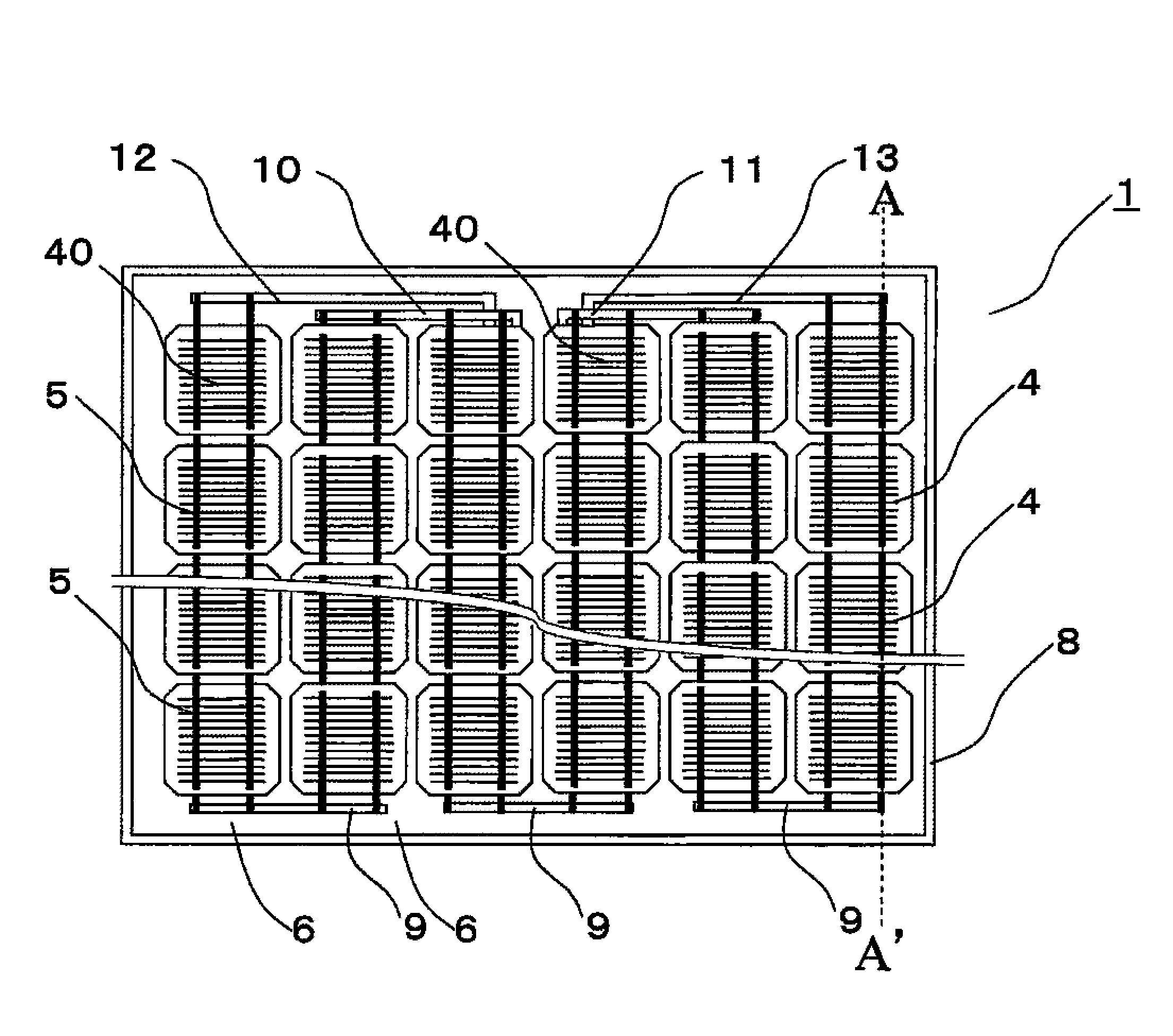
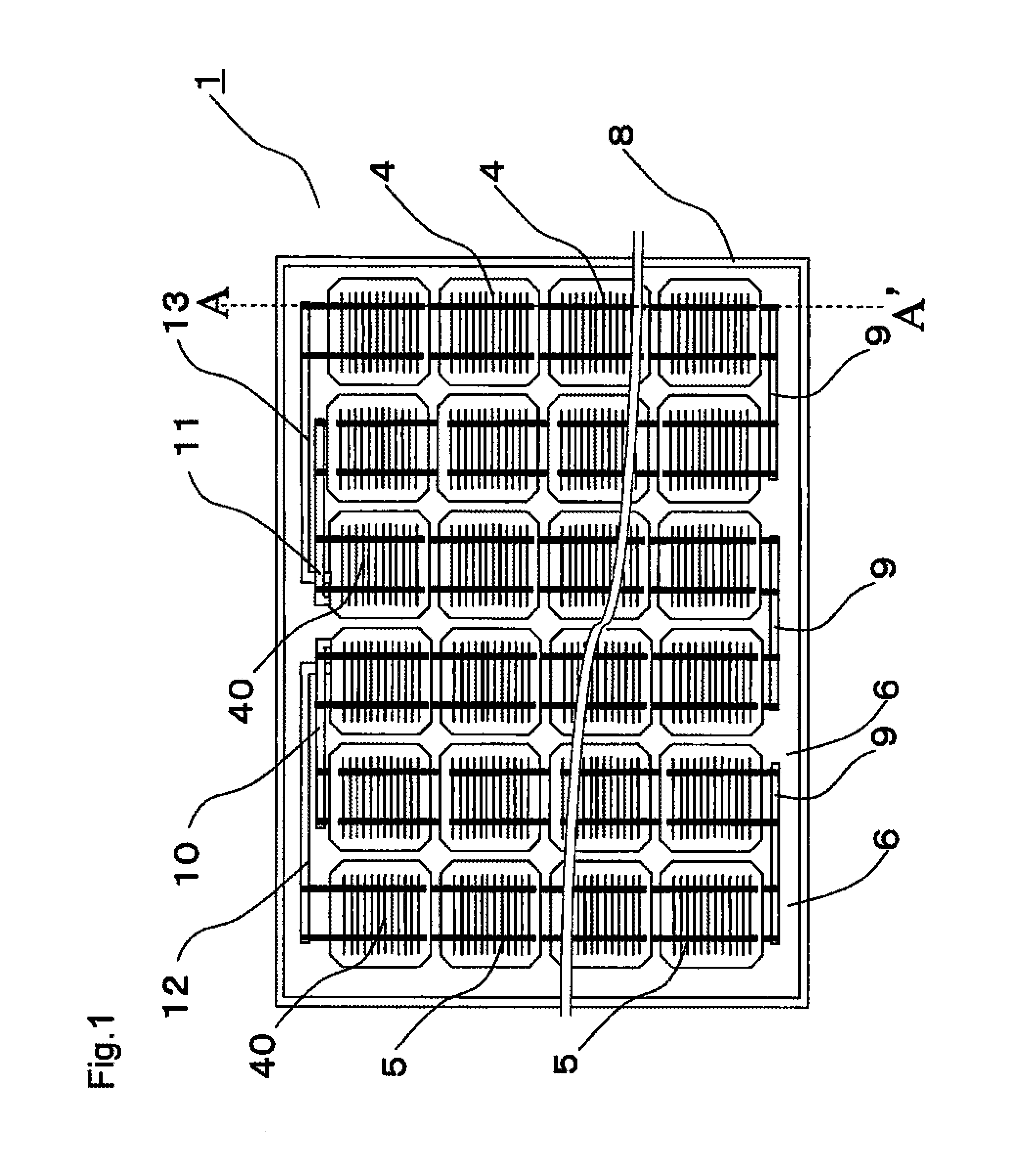
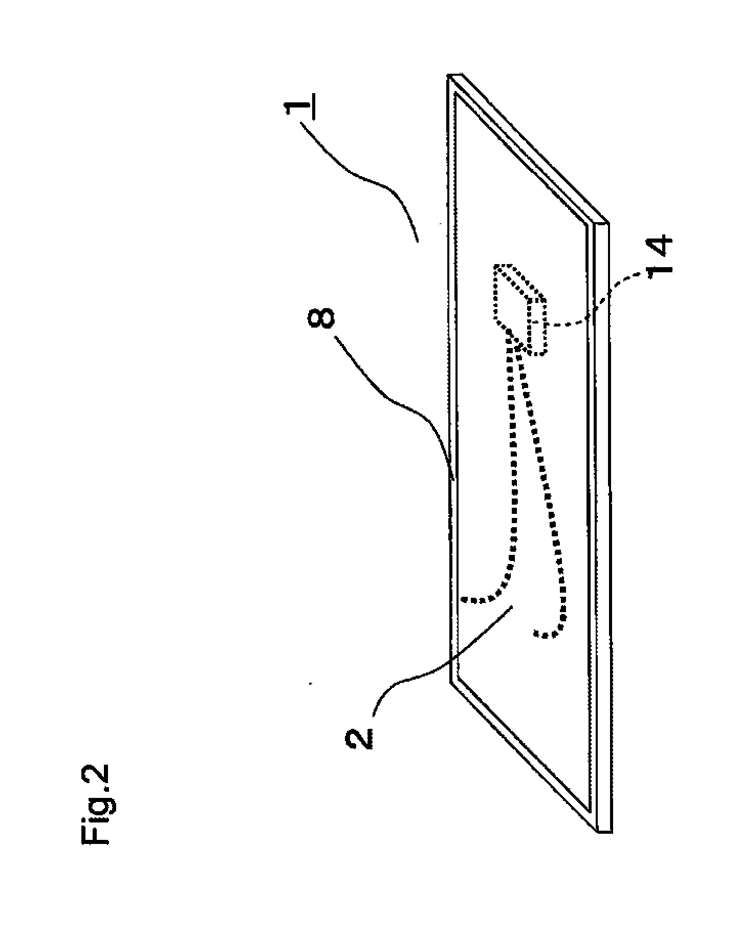
[0048]A solar cell module including a plurality of solar cells according to a first embodiment of the invention is described with reference to FIGS. 1 to 6B. FIG. 1 is a top view of the solar cell module according to the first embodiment of the invention. FIG. 2 is a perspective view of the solar cell module. FIG. 3 is a partial cross-sectional view taken along the line A-A′ of FIG. 1. FIG. 4A is a top view of the solar cell of the solar cell module of FIG. 1. FIG. 4B is a bottom view of the solar cell. FIG. 5A is a front side plan view provided for describing the connection between the solar cell and conductive connection members. FIG. 5B is a partial schematic cross-sectional view taken along the line A-A′ of FIG. 5A. FIG. 6A is a partial schematic cross-sectional view taken along the line B-B′ of FIG. 5A. FIG. 6B is a partial schematic cross-sectional view taken along the line C-C′ of FIG. 5A.

[0049]As shown in FIGS. 1 through 3, solar cell module 1 includes a rectangular plate-li...

second embodiment

[0087]A solar cell module according to a second embodiment of the invention is described with reference to FIGS. 8A and 8B. FIG. 8A is a top view of a solar cell in the solar cell module according to this embodiment. FIG. 8B is a bottom view of the solar cell. Here, differences from the first embodiment are mainly described.

[0088]Referring to FIGS. 8A and 8B, each of solar cells 4 has front surface electrode 40 including a plurality of narrow linear finger electrodes 40a disposed on the front surface thereof so as to cover substantially the entire front surface region, and two narrow saw-tooth like bus bar electrodes 140b connected to the plurality of narrow finger electrodes 40a. In addition, each of solar cells 4 has rear surface electrode 41 including a plurality of narrow linear finger electrodes 41a disposed on the rear surface thereof so as to cover substantially the entire rear surface region, and two narrow saw-tooth like bus bar electrodes 141b connected to the plurality of...

third embodiment

[0098]A solar cell module according to a third embodiment of the invention is described with reference to FIGS. 9A and 9B. FIG. 9A is a top view of a solar cell in the solar cell module according to this embodiment. FIG. 9B is a bottom view of the solar cell. Here, differences from the first embodiment are mainly described.

[0099]Referring to FIGS. 9A and 9B, each of solar cells 4 has front surface electrode 40 including a plurality of narrow linear finger electrodes 40a disposed on the front surface thereof so as to cover substantially the entire front surface region, and two narrow wave like bus bar electrodes 240b connected to the plurality of narrow linear finger electrodes 40a. Each narrow linear finger electrode 40a has width Wf equal to 60 μm, and each narrow wave like bus bar electrode 240b has width W equal to 1.5 mm, for example. In addition, each of solar cells 4 has rear surface electrode 41 including a plurality of narrow linear finger electrodes 41a disposed on the rear...


PUM


Abstract

A solar cell includes: a front surface electrode having a first current-collecting electrode and non-straight line electrodes connected to the first current-collecting electrode; a semiconductor substrate serving as a photoelectric conversion body; and a rear surface electrode having a second current-collecting electrode and line electrodes connected to the second current-collecting electrode. The front surface electrode, the semiconductor substrate and the rear surface electrode are arranged in that order. The non-straight line electrodes of the front surface electrode and the line electrodes of the rear surface electrodes are opposed to each other with the semiconductor substrate interposed there-between. The non-straight line electrodes of the front surface electrode and the line electrodes of the rear surface electrodes are different in shape while having a portion where the electrodes intersect each other, as seen in a direction perpendicular to the front surface of the semiconductor substrate.

Description

CROSS REFERENCE TO RELATED APPLICATIONS[0001]This application of the invention titled “Solar Cell, Solar Cell Module and Solar Cell System” is based upon and claims the benefit of priority under 35 USC 119 from prior Japanese Patent Application No. 2009-085599, filed on Mar. 31, 2009; the entire contents of which are incorporated herein by reference.BACKGROUND OF THE INVENTION[0002]1. Field of the Invention[0003]The invention relates to a solar cell, a solar cell module and a solar cell system.[0004]2. Description of the Related Art[0005]A solar cell system provided with solar cells is expected to be a new energy conversion system that converts light from the sun into electricity. In recent years, active use of solar cell systems has been increasing as a general household power supply and a large-scale power generation plant.[0006]Currently research and development for cost reduction of solar cell systems is actively in progress in order to further spread the use solar cell systems....

Claims


Application Information

Patent Timeline
Patent Type & Authority Applications(United States)
IPC IPC(8): H01L31/042H01L31/00
CPCH01L31/042Y02E10/50H01L31/0512H01L31/022433H01L31/0747H01L31/0201
Inventor HASHIMOTO, HARUHISAISHIGURO, TASUKU
Owner PANASONIC INTELLECTUAL PROPERTY MANAGEMENT CO LTD
Why Eureka
Try Eureka