Resistance welding method and resistance welding apparatus

a welding apparatus and resistance welding technology, applied in the direction of manufacturing tools, electrode features, electric/magnetic/electromagnetic heating, etc., can solve the problems of insufficient growth, insufficient joule heat generation insufficient growth of the thinnest workpiece, so as to achieve a simple control process

Active Publication Date: 2010-09-30
HONDA MOTOR CO LTD
View PDF1 Cites 25 Cited by
  • Summary
  • Abstract
  • Description
  • Claims
  • Application Information

AI Technical Summary

Benefits of technology

[0013]A general object of the present invention is to provide a resistance welding method, which through a simple control process is capable of sufficiently growing a nugget between a thinnest workpiece on an outermost side of a stacked assembly and a workpiece disposed adjacent to the thinnest workpiece.

Problems solved by technology

If the stacked assembly of metal sheets is resistance welded with the thinnest workpiece disposed on an outermost side of the stacked assembly, then the nugget, which is formed between the thinnest workpiece and a workpiece adjacent thereto, may not grow sufficiently.
The reason for insufficient growth of the nugget is considered to be based on the fact that since the thickness of the thinnest workpiece is the smallest and its specific resistance is minimum, the thinnest workpiece fails to generate a sufficient amount of Joule heat.
However, in this case, large electric current tends to flow through a workpiece of a larger thickness, and thus, such an increased electric current tends to unduly melt the workpiece, thus producing scattering of metal particles and resulting in sputtering.
However, in this case also, it is difficult to generate sufficient Joule heat in the thinnest workpiece.
Additionally, a longer welding time results in a lower welding efficiency, disadvantageously.

Method used


Image

  • Resistance welding method and resistance welding apparatus
  • Resistance welding method and resistance welding apparatus
  • Resistance welding method and resistance welding apparatus

Examples


Embodiment Construction

[0038]A resistance welding method will be described in detail below with reference to the accompanying drawings, in connection with a resistance welding apparatus, which carries out the resistance welding method according to an embodiment of the present invention.

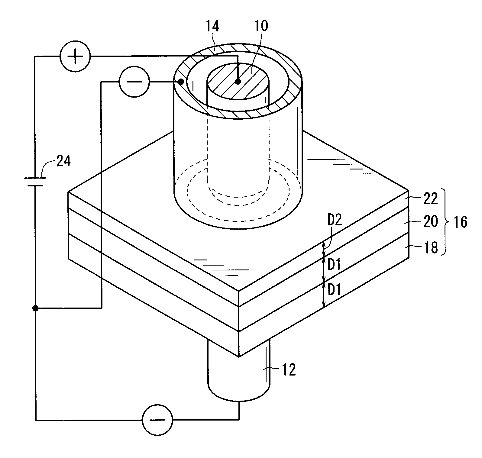
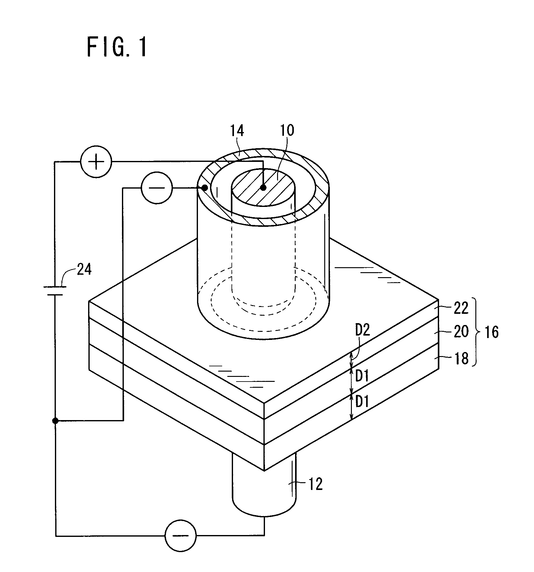
[0039]FIG. 1 is a perspective view, partially in transverse cross-section, of a resistance welding apparatus according to an embodiment of the present invention. As shown in FIG. 1, the resistance welding apparatus comprises a welding gun, not shown, having a first electrode tip 10 serving as a first welding electrode, a second electrode tip 12 serving as a second welding electrode, and a current branching electrode 14. The welding gun is mounted on a tip end of an arm of an articulated robot, such as a six-axis robot or the like. Such an articulated robot, with a welding gun mounted on the arm thereof, is well known in the art and will not be described in detail below.

[0040]The resistance welding apparatus serves to weld a...


PUM

PropertyMeasurementUnit
thickness D1aaaaaaaaaa

Abstract

A resistance welding apparatus includes a welding gun having a first electrode tip serving as a first welding electrode, a second electrode tip serving as a second welding electrode, and a current branching electrode. The current branching electrode has an annular shape and is disposed in surrounding relation to the first electrode tip. The first electrode tip and the current branching electrode abut against a thinnest workpiece disposed on an outermost side of a stacked assembly that is resistance-welded by the resistance welding apparatus, and have opposite polarities to each other. When an electric current is passed from the first electrode tip to the second electrode tip and through the stacked assembly, a branched electric current flows from the first electrode tip to the current branching electrode.

Description

CROSS-REFERENCE TO RELATED APPLICATION[0001]This application is based upon and claims the benefit of priority from Japanese Patent Applications No. 2009-087946 filed on Mar. 31, 2009 and No. 2010-061024 filed on Mar. 17, 2010, of which the contents are incorporated herein by reference.BACKGROUND OF THE INVENTION[0002]1. Field of the Invention[0003]The present invention relates to a resistance welding method and a resistance welding apparatus for resistance-welding a stacked assembly made up of three or more workpieces, including a thinnest workpiece which is disposed on an outermost side of the stacked assembly.[0004]2. Description of the Related Art[0005]One known process for joining a plurality of metal sheets to each other is a resistance welding process, in which the metal sheets are stacked in a stacked assembly. Then, after the stacked assembly has been gripped and pressed by a set of welding electrodes, an electric current is passed between the welding electrodes in order to ...

Claims


Application Information

Patent Timeline
Patent Type & Authority Applications(United States)
IPC IPC(8): B23K11/30B23K11/00
CPCB23K11/0026B23K11/30B23K11/115
Inventor GOTO, AKIRA
Owner HONDA MOTOR CO LTD
Why Eureka
Try Eureka