Mapping mechanism, foup and load port

Inactive Publication Date: 2010-09-30
SINFONIA TECHNOLOGY CO LTD
View PDF1 Cites 6 Cited by
  • Summary
  • Abstract
  • Description
  • Claims
  • Application Information

AI Technical Summary

Benefits of technology

[0010]Therefore, it is a principal object of the present invention to provide a mapping mechanism which can carry out a mapping process appropriately without opening a lid member of a FOUP and can achieve simplification in structure and suppression of unnecessary increase of the cost.
[0018]According to the present invention, a mapping mechanism can be provided which can carry out a mapping process for a FOUP rapidly and accurately without opening the lid member of the FOUP and can achieve simplification in structure and suppression of unnecessary increase of the cost.

Problems solved by technology

However, in the mode disclosed in Patent Document 1, since the wafer detecting door is pressed by the detection sensors every time a mapping process is carried out, there is the possibility that the sensors themselves may be damaged by the load and so forth upon such pressing, and it is difficult to maintain a appropriate mapping processing function for a long period of time.
Further, the provision itself of the transmission type sensors in a comb-like arrangement in the heightwise direction gives rise to complication of the structure.
Thus, there is another problem that, if the accuracy of the pitch of the transmission sensors is low, then the transmission type sensors may be brought into contact with wafers to disable an appropriate mapping process.
Meanwhile, in the mode disclosed in Patent Document 2, since the image pickup system is essentially required, a high cost is required.
Therefore, there is a problem that the accuracy and reliability of the mapping process are deteriorated by the influence.
Further, also with the mode disclosed in Patent Document 3 which uses a pair of reflection type sensors, if the type or the like of wafers changes and also the reflection factor changes, then it is likewise difficult to carry out a mapping process always with a high degree of accuracy.

Method used


Image

  • Mapping mechanism, foup and load port
  • Mapping mechanism, foup and load port
  • Mapping mechanism, foup and load port

Examples


first embodiment

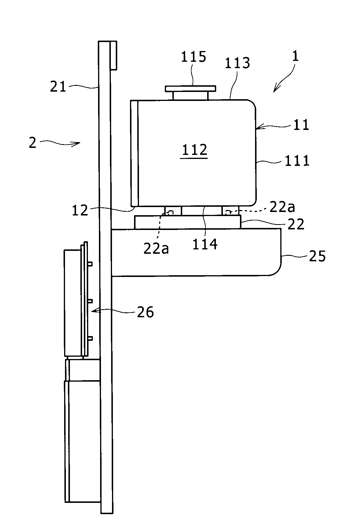
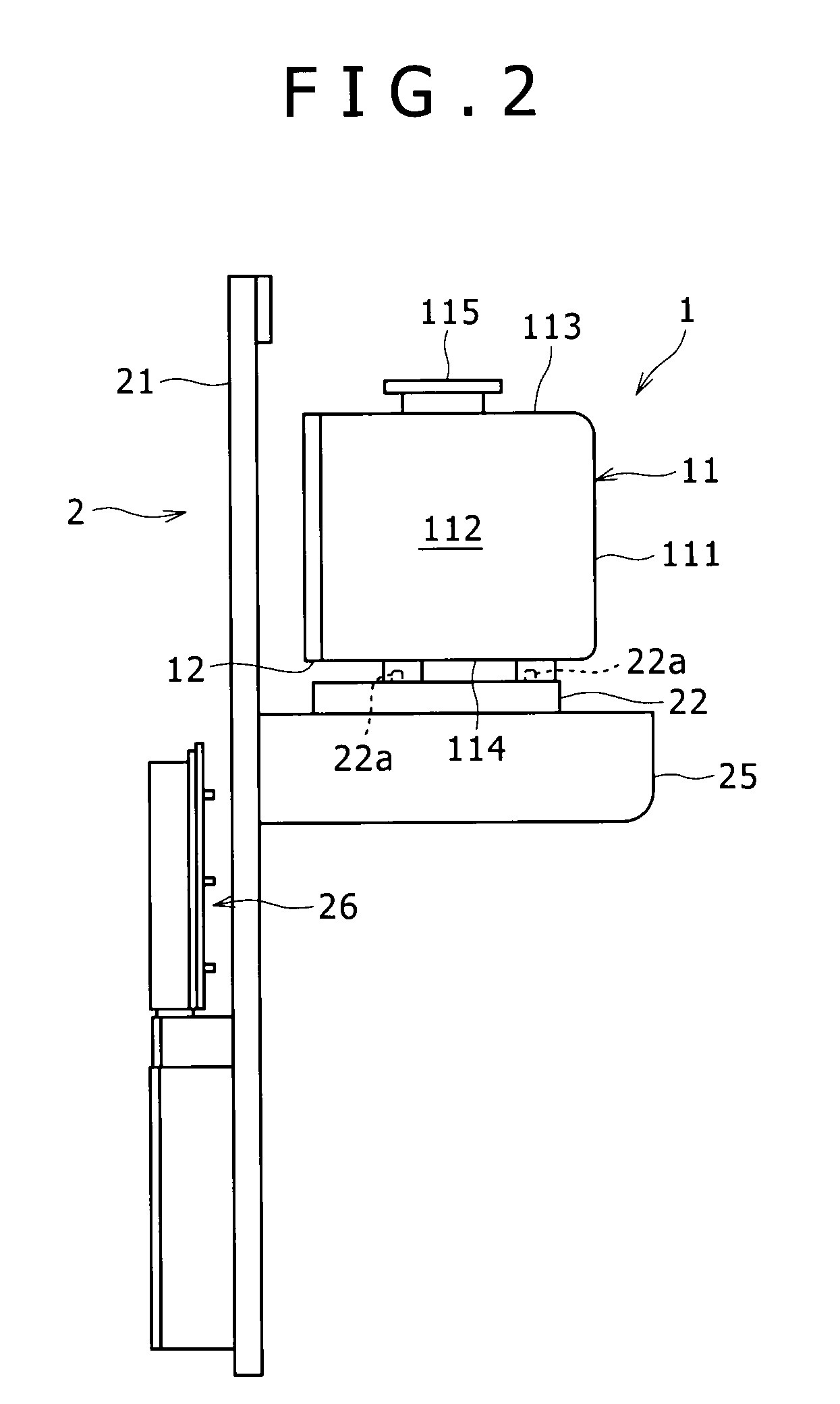
[0026]A mapping mechanism M according to a first embodiment of the present invention carries out mapping for a FOUP 1 and includes a light emitting member 241 and a light receiving member 242 provided on a load port 2, and a window member such as a first window member 12B and a second window member 12C provided on a light path L between the light emitting member 241 and the light receiving member 242 in the FOUP 1 as seen in FIG. 4.

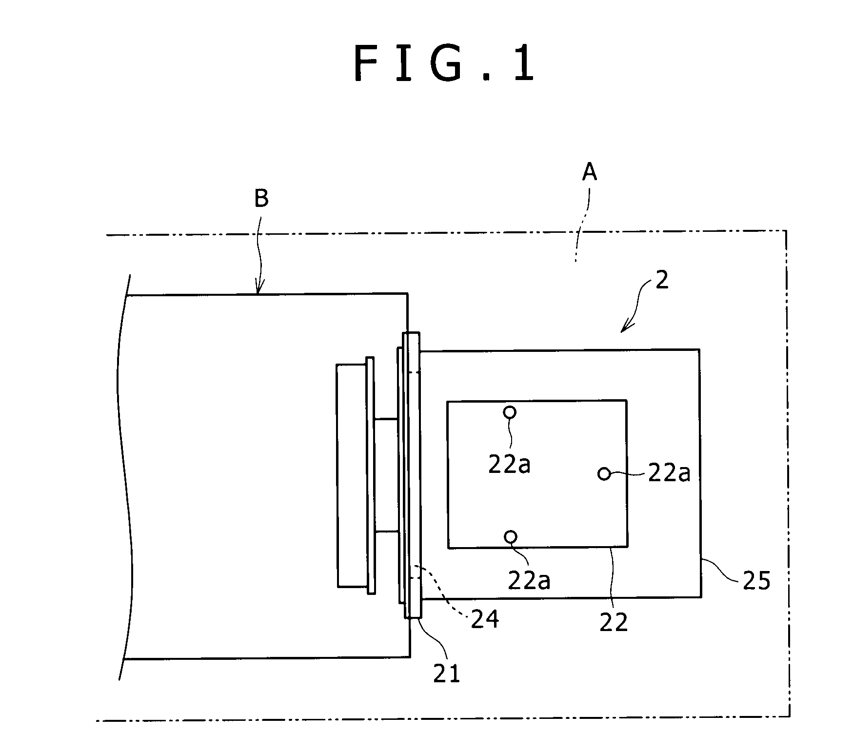
[0027]The load port 2 is used in a fabrication process of semiconductors and is disposed in the proximity of a semiconductor fabrication apparatus B in a common clean room A as seen in FIGS. 1 to 3. The load port 2 is closely contacted with a lid member 12 of the FOUP 1 to open and close the lid member 12 and carries a wafer W between the inside of the FOUP 1 and the inside of the semiconductor fabrication apparatus B. FIG. 1 is a plan view showing the load port 2 and associated members as viewed from above and schematically illustrates a relative positio...

second embodiment

[0041]A mapping mechanism XM according to a second embodiment of the present invention is similar to the mapping mechanism M according to the first embodiment in that a light emitting member X241 and a light receiving member X242 are provided on a door member X24 of a load port X2 as seen in FIGS. 5 and 6 but is different in the following points. In particular, the light emitting member X241 and the light receiving member X242 project forwardly from a front face of the door member X24, that is, toward the FOUP X1 side. Further, a pair of recessed portions, that is, a first recessed portion X12F and a second recessed portion X12G, are formed on the lid member X12 of the FOUP X1 such that the light emitting member X241 and the light receiving member X242 projecting from the front face of the door member X24 can be inserted into the recessed portions, that is, the first recessed portion X12F and the second recessed portion X12G, respectively, and the window portions, that is, the first...


PUM


Abstract

Disclosed herein is a mapping mechanism for carrying out mapping for a FOUP which includes a wafer receiving section on which a plurality of wafers can be placed at a plurality of stages in a heightwise direction and a lid member mounted for opening and closing movement, including: a light emitting member and a light receiving member provided outside the FOUP; and a window member provided on a light path between the light emitting member and the light receiving member which can cross at least part of the wafers placed on the stage portions of the wafer receiving section; the light being caused to pass over all of the stages of the wafer receiving section of the FOUP to carry out the mapping for the FOUP.

Description

BACKGROUND OF THE INVENTION[0001]1. Field of the Invention[0002]This invention relates to a mapping mechanism for carrying out mapping for a FOUP (Front-Opening Unified Pod).[0003]2. Description of the Related Art[0004]In a fabrication process of semiconductors, processing of a wafer in a clean room is used in order to assure a high yield and high quality. However, in this day in which high integration of devices, refinement of circuitry and increase in size of wafers advance, it is difficult in terms of the cost and the technology to manage fine dust in the entire inside of the clean room. Therefore, in recent years, as a method which replaces the improvement in cleanness of the entire inside of the clean room, a countermeasure is adopted which introduces a “mini environment method” which improves the cleanness only in a local space around a wafer to carry out transportation and other processes of the wafer. In the mini environment method, a containment called FOUP (Front-Opening U...

Claims


Application Information

Patent Timeline
IPC IPC(8): H01J40/14
CPCH01L21/67772H01L21/67265
Inventor SUZUKI, KENSUKEKAMIGAKI, TOSHIOMIENO, YASUMICHI
Owner SINFONIA TECHNOLOGY CO LTD
Why Eureka
Try Eureka