Connection structure and assembly method of tube-shaped frames

a tube-shaped frame and assembly method technology, applied in the directions of roofs, transportation and packaging, vehicle arrangements, etc., can solve the problem of improperly reducing the rigidity of the tube-shaped fram

Inactive Publication Date: 2010-09-30
MAZDA MOTOR CORP
View PDF17 Cites 54 Cited by
  • Summary
  • Abstract
  • Description
  • Claims
  • Application Information

AI Technical Summary

Benefits of technology

[0008]Accordingly, an object of the present invention is to provide a connection structure of tube-shaped frames in which the tube-shaped frames can be connected properly without forming any hole at the wall of the tube-shaped frame.

Problems solved by technology

However, this though hole formed may decrease the rigidity of the tube-shaped frame improperly.

Method used


Image

  • Connection structure and assembly method of tube-shaped frames
  • Connection structure and assembly method of tube-shaped frames
  • Connection structure and assembly method of tube-shaped frames

Examples


embodiment 1

Embodiment 1

FIGS. 1 and 2

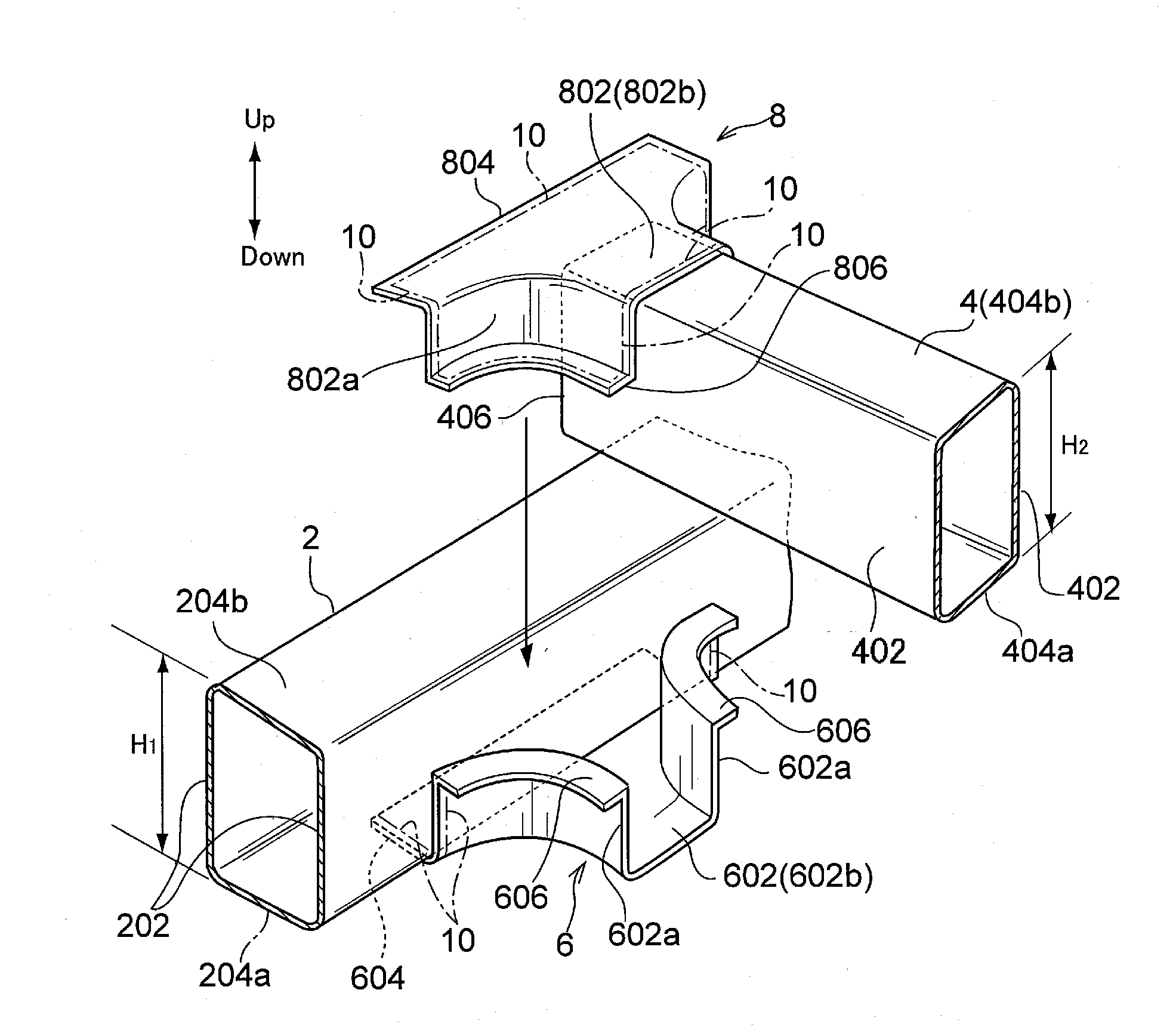
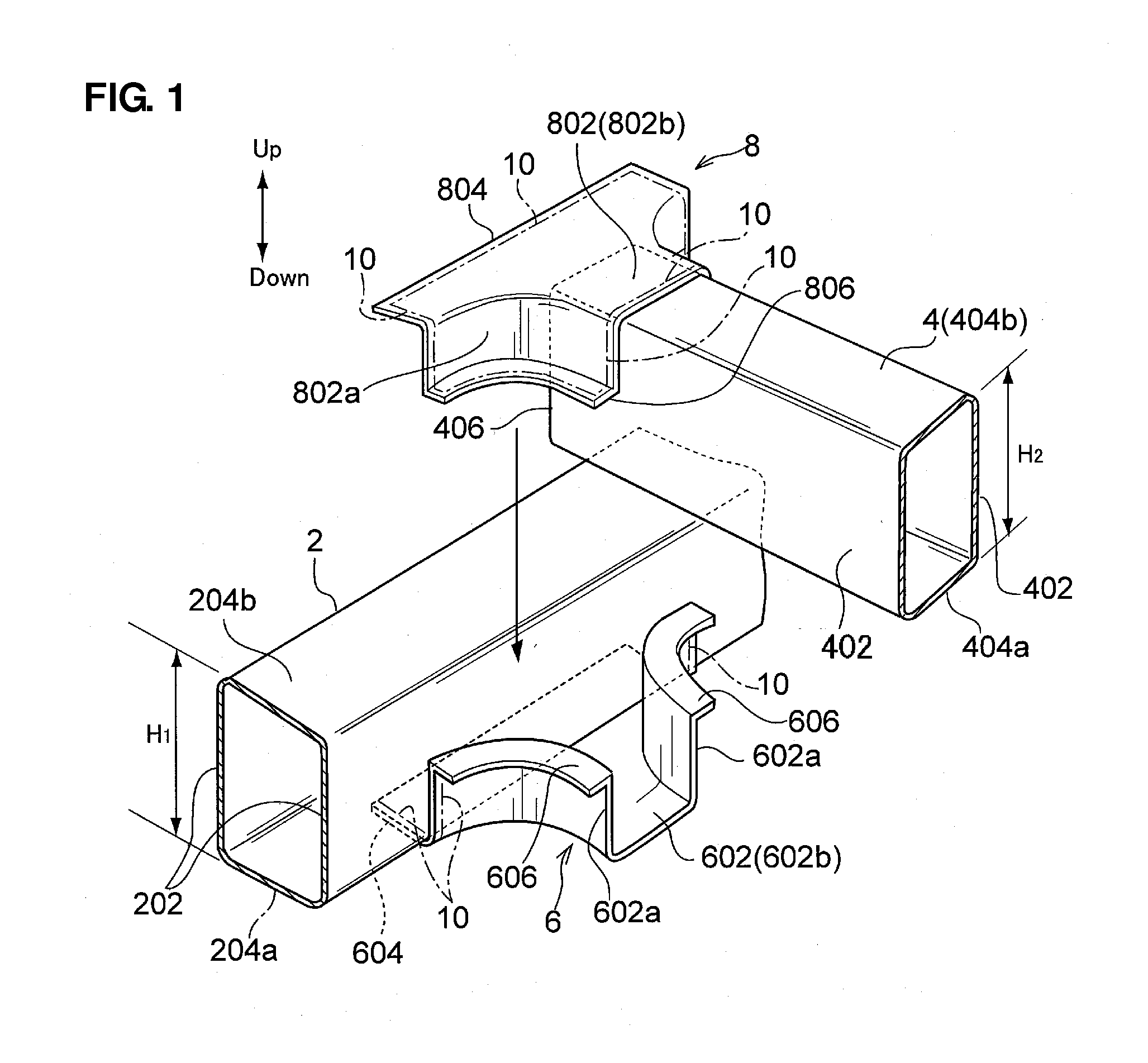
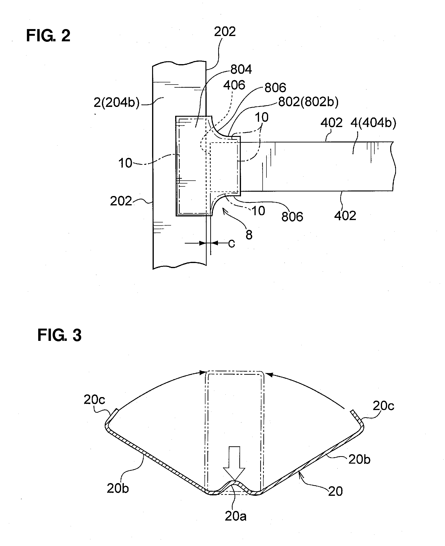
[0068]A first embodiment shows a connection structure in which first and second tube-shaped frames 2, 4 are connected in a T shape. The first and second tube-shaped frames 2, 4 have a structure having a closed rectangular cross section, respectively, which include two side walls 202, 402 which face to each other and end walls 204, 404 which face to each other. Of course, while the first and second tube-shaped frames 2, 4 shown in the figures have a conceptual shape which may be preferable for explanation, any concrete sectional shape may be applicable. Further, the first and second tube-shaped frames 2, 4 shown in the figures have the same height H1, H2 (H1=H2), but they may have different heights.

[0069]While the first and second tube-shaped frames 2, 4 are arranged perpendicularly to each other in the example shown in the figures, this crossing angle of these frames 2, 4 is not limited to 90 degrees. The specific connection structure of the first and second...

second embodiment

[0102 of Connection Structure (FIGS. 12-14)

[0103]According to the connection structure of the second embodiment, a second tube-shaped frame 50 which connects to the side wall of the first tube-shaped frame 2 is comprised of two split-frames 52, 54 which have the U-shaped cross section as shown in FIGS. 7 and 8. The lower split-frame 54 has a pair of flanges 54a which project outwardly. Herein, the above-described first split-bracket 6 is formed integrally with this lower split-frame 54, which is apparent from FIG. 14. Herein, of course, the lower first split-bracket 6 which is formed integrally with the lower split-frame 54 may be the embodiment of FIG. 1.

third embodiment

[0104 of Connection Structure (FIGS. 15-18)

[0105]FIGS. 15-18 show another embodiment, a third embodiment, in which a protruding portion 60 is provided at each of the borders between the bracket bodies 602, 802 and the enclosing portions 608, 808 of the first and second split-brackets 6, 8. The third embodiment shown here is based on the split-brackets 6, 8 of the above-described modification of the first embodiment (FIGS. 9-11). However, the feature of the third embodiment may be applied to the above-described first embodiment (FIG. 1) or the second embodiment (FIGS. 12-14) as well.

[0106]Modification of Third Embodiment (FIGS. 19 and 20)

[0107]The protruding portions 60 of FIGS. 15-18 of the third embodiment may be configured to extend in the split enclosing portions 608, 808 of the split-brackets 6, 8 in an extending direction of the first tube-shaped frame 2. Further, second protruding portions 62 may be provided at the upper end wall 204b and the lower end wall 204a of the first t...


PUM

PropertyMeasurementUnit
crossing angleaaaaaaaaaa
connection structureaaaaaaaaaa

Abstract

A first split-bracket is joined to a first tube-shaped frame by lazar welding. A second split-bracket is joined to an end portion of a second tube-shaped frame by the lazar wielding. The second tube-shaped frame equipped with the second split-bracket is assembled to the first tube-shaped frame equipped with the first split-bracket. A second flange of the first split-bracket and a second flange of the second split-bracket are joined temporarily by spot welding. The second flange of the first split-bracket and the second flange of the second split-bracket are joined by continuous welding with lazar welding. Accordingly, the tube-shaped frames can be connected properly without forming any hole at a wall of the tube-shaped frame, ensuring the rigidity of the connection portion of the tube-shaped frames.

Description

BACKGROUND OF THE INVENTION[0001]The present invention relates to a connection structure and assembly method of tube-shaped frames.[0002]The use of a tube-shaped frame has been developed to improve the rigidity of a vehicle body or others despite a relatively small area of a closed cross section of the tube-shaped frame.[0003]Japanese Patent Laid-Open Publication No. 62-173378 discloses the structure in which the front pillar is comprised of the outer panel and the tube-shaped frame, and the outer pillar has the flange which is equipped with the door seal strip. This tube-shaped frame is comprised of the tube which is made by the hydro-forming and has the substantially hexagonal cross section, and the base portion of the outer panel is joined to the flat front face portion of the tube-shaped frame so that the windshield is supported at the base portion of the outer panel.[0004]Japanese Patent Laid-Open Publication No. 2006-182079 discloses the proposal in that the hollow member with...

Claims


Application Information

Patent Timeline
Patent Type & Authority Applications(United States)
IPC IPC(8): B62D21/00B21D53/88
CPCB62D21/02B62D21/08B62D23/005B62D27/023Y10T29/49622B62D33/044B60G2204/43B60G2204/44B60G2206/604B62D29/008
Inventor HONDA, MASANORISASAKI, SHINHASHIDA, TAKAYUKI
Owner MAZDA MOTOR CORP
Why Eureka
Try Eureka