Vehicle braking system and master cylinder
a brake system and master cylinder technology, applied in brake systems, rotary clutches, fluid couplings, etc., can solve the problem of difficult to obtain a good pedal feel over a larger range, and achieve the effect of good pedal feel
- Summary
- Abstract
- Description
- Claims
- Application Information
AI Technical Summary
Benefits of technology
Problems solved by technology
Method used
Image

Examples
first embodiment
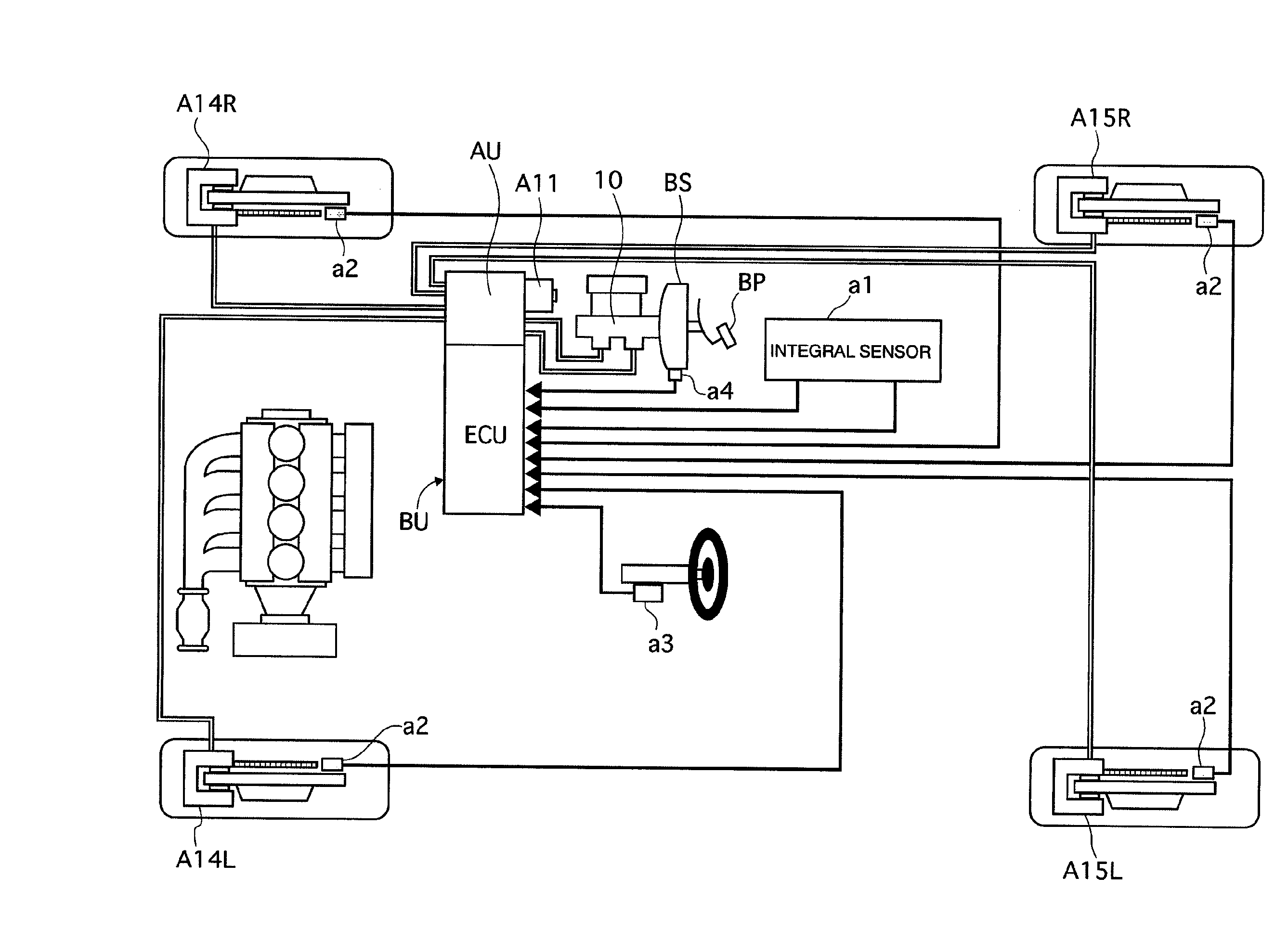
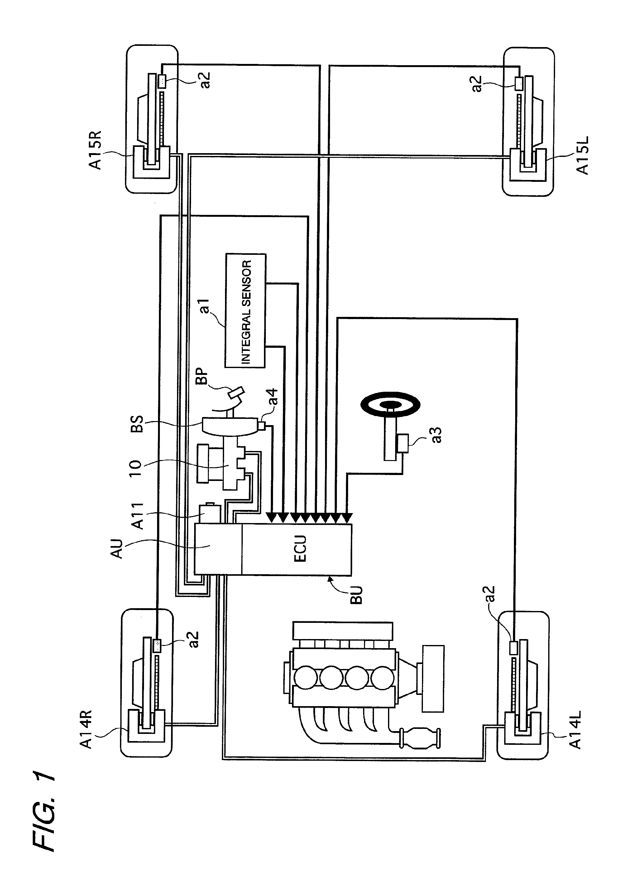
[0018]First, a configuration of a first embodiment is described referring to FIG. 1. A brake control unit BU according to the first embodiment includes: an integral sensor a1 which detects a yaw rate, a lateral acceleration, and a longitudinal acceleration of a vehicle; wheel-speed sensors a2; a steering-angle sensor a3 which detects a steering angle of a steering wheel steered by a driver; a negative-pressure sensor a4 which detects a negative pressure of a booster BS; and a hydraulic-pressure sensor a5 which detects a hydraulic pressure generated in a pressure chamber (small-diameter pressure chamber 61) of a master cylinder 10 (FIG. 2). The hydraulic pressure output from the brake control unit BU is supplied to wheel cylinders A14 (A14L, A14R) and A15 (A15L, A15R) of the respective wheels to achieve a desired braking force.
[0019]A pressing force input to a brake pedal BP operated by the driver is assisted by the booster BS, and the thus assisted piston-pushing force is transmitte...
second embodiment
[0158]In the first embodiment described above, the hydraulic pressure corresponding to 2.5 m / s2 is set to 2.3 MPa, and the hydraulic pressure at which the control valve 75 functioning as the pressure-reducing valve is opened is set as high as about 4 MPa. However, the valve-opening pressure for the control valve 75 is not limited thereto. The hydraulic pressure corresponding to 2.5 m / s2 may be set to a lower value within the aforementioned hydraulic-pressure range of 1.7 MPa to 2.9 MPa, for example, to 1.7 MPa so that the hydraulic pressure at which the control valve 75 is opened may be set to 2 MPa.
[0159]In the case of the setting as described above, the relation between the pressing force (muscle force) and the master cylinder hydraulic pressure is as shown in FIG. 10. When the booster BS operates normally, the assist force is generated by the booster BS as a result of the generation of the pressing force on the brake pedal by the driver. Then, the driver can obtain the master cyl...
PUM
 Abstract
Description
Claims
Application Information
 - R&D
- Intellectual Property
- Life Sciences
- Materials
- Tech Scout
- Unparalleled Data Quality
- Higher Quality Content
- 60% Fewer Hallucinations
Browse by: Latest US Patents, China's latest patents, Technical Efficacy Thesaurus, Application Domain, Technology Topic, Popular Technical Reports.
© 2025 PatSnap. All rights reserved.Legal|Privacy policy|Modern Slavery Act Transparency Statement|Sitemap|About US| Contact US: help@patsnap.com