Multicarrier transmitter and multicarrier receiver

a multi-carrier transmitter and receiver technology, applied in power management, orthogonal multiplex, polarisation/directional diversity, etc., can solve problems such as deterioration in reception performance, and achieve the effect of improving the reception performance in hierarchical modulation multiplexing communication

Inactive Publication Date: 2010-09-30
PANASONIC CORP
View PDF8 Cites 49 Cited by
  • Summary
  • Abstract
  • Description
  • Claims
  • Application Information

AI Technical Summary

Benefits of technology

[0023]According to the present invention, it is possible to provide a multicarrier transmitting apparatus and multicar

Problems solved by technology

As a result, there is a possibility th

Method used


Image

  • Multicarrier transmitter and multicarrier receiver
  • Multicarrier transmitter and multicarrier receiver
  • Multicarrier transmitter and multicarrier receiver

Examples


embodiment 1

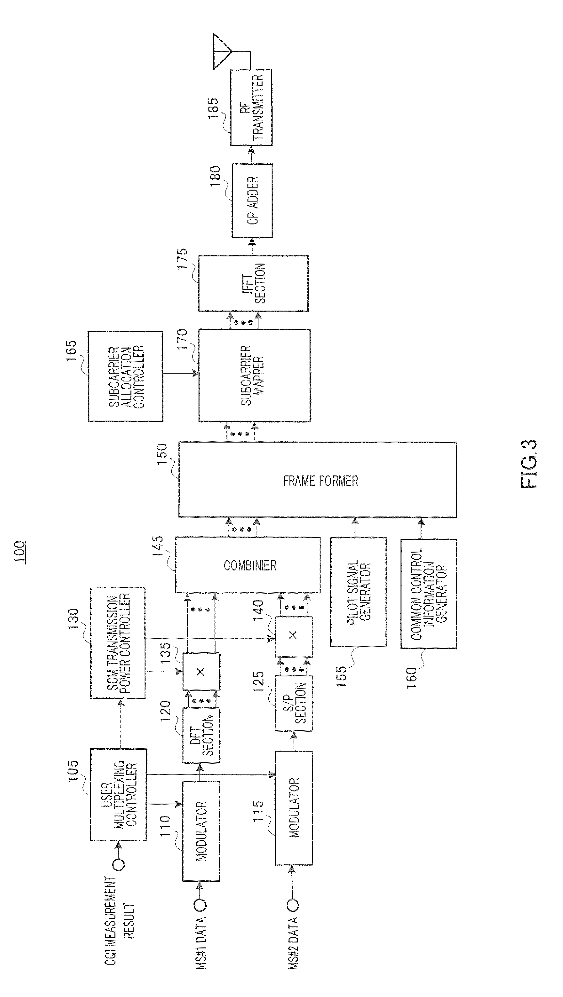
[0047]As shown in FIG. 3, base station apparatus 100 that is a multicarrier transmitting apparatus according to the present embodiment has user multiplexing controller 105, modulator 110, modulator 115, DFT (Discrete Fourier Transform) section 120, S / P section 125, SCM transmission power controller 130, multiplier 135, multiplier 140, combiner 145, frame former 150, pilot signal generator 155, common control information generator 160, subcarrier allocation controller 165, subcarrier mapper 170, IFFT section 175, CP adder 180 and RF transmitter 185.

[0048]Further, FIG. 3 shows the configuration of base station apparatus 100 in case where OFDMA is applied. Hereinafter, a case will be explained where SCM transmission is performed using N1 subcarriers. Here, in case where N_FFT is assumed to be the FFT size in the IFFT (Inverse Fast Fourier Transform) section, the relationship N1≧N_FFT holds.

[0049]Based on CQI (Channel Quality Information) which is the measurement result of channel quali...

embodiment 2

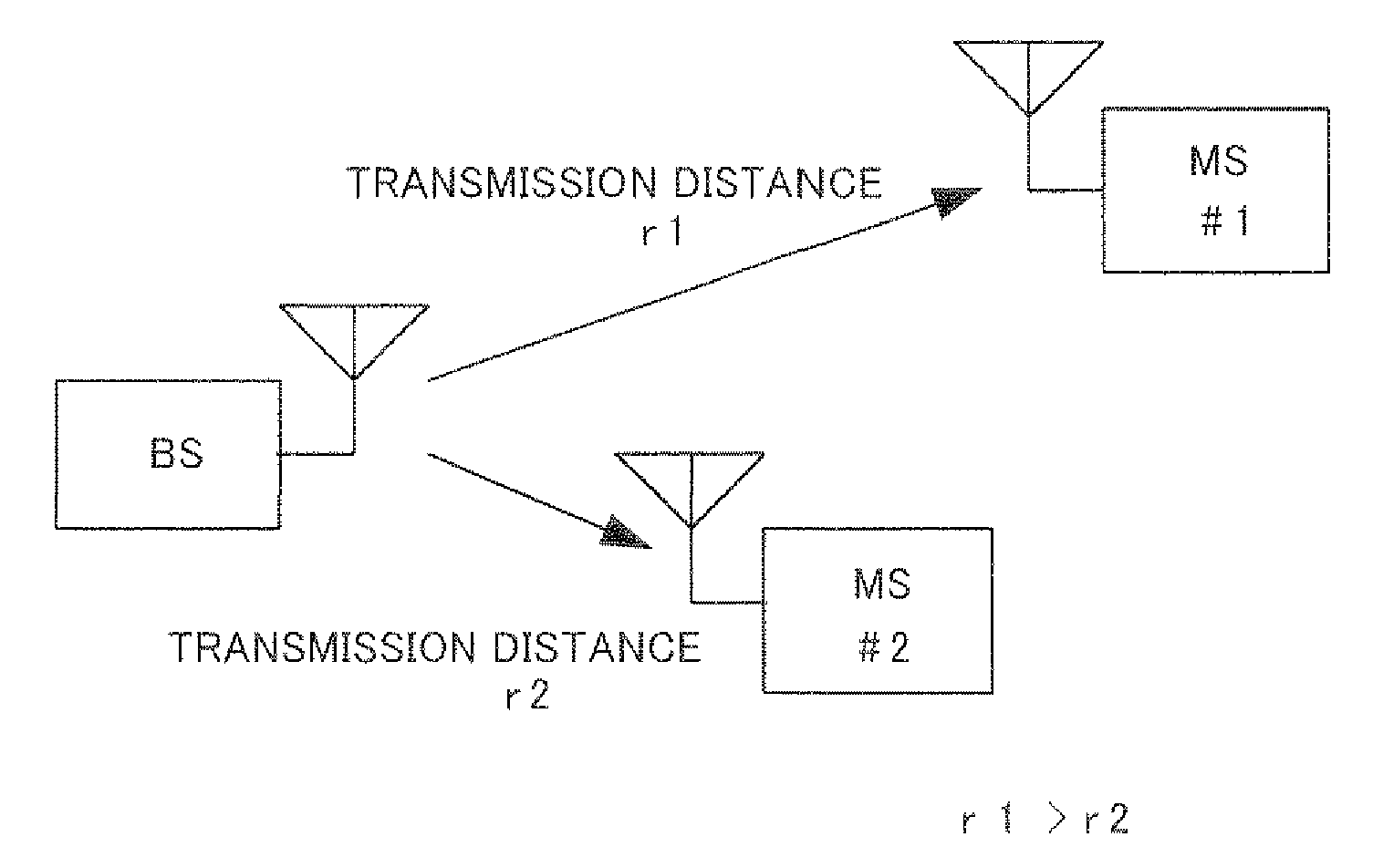
[0140]The present embodiment is the same as Embodiment 1 in transmitting a signal in which a second modulated signal is superimposed as is as a time domain signal upon a plurality of frequency components into which a first modulated signal is divided in the frequency domain on a per symbol basis. However, while, with Embodiment 1, the first modulated signal and the second modulated signal are addressed to the distant user and nearby user, respectively, with the present embodiment, the first modulated signal and second modulated signal are addressed to the nearby user and distant user, respectively.

[0141]That is, the base station apparatus according to the present embodiment has the same configuration as base station apparatus 100 shown in FIG. 3. However, modulator 110, DFT section 120 and multiplier 135 process signals addressed to the nearby user, and modulator 115, S / P section 125 and multiplier 140 process signals addressed to the distant user. Therefore, transmission power coef...

embodiment 3

[0172]FIG. 11 is a block diagram showing a configuration of base station apparatus 600 that is a multicarrier transmitting apparatus according to Embodiment 3. Similar to base station apparatus 100, base station apparatus 600 transmits a signal in which the second modulated signal is superimposed as is as a time domain signal upon a plurality of frequency components into which the first modulated signal is divided in the frequency domain on a per symbol basis.

[0173]Note that, as shown in FIG. 11, base station apparatus 600 differs from base station apparatus 100 in the configuration as follows. That is, base station apparatus 600 has: DFT output power measurer 610 that measures amplitudes of subcarriers outputted from DFT section 120 every predetermined subcarrier blocks for a predetermined period; subcarrier mapping determiner 620 that determines subcarriers to map output modulated signals acquired by modulating outputs of DFT section 120 based on the outputs of DFT output power me...


PUM


Abstract

A multicarrier transmitter and a multicarrier receiver both enabling improvement of the reception characteristic of hierarchical modulation multiplex communication. A base station (100) transmits a multicarrier signal which is a superposition of a modulated signal addressed to a far user and a modulated signal addressed to a near user and modulated with a modulation multivalued number different from that of the modulated signal addressed to the far user. The base station (100) comprises a DFT section (120), an S/P section (125), and a combining section (145). The DFT section (120) separates the modulated signal addressed to the far user into signals in frequency ranges for each symbol. The S/P section (125) serial/parallel-transforms the modulated signal addressed to the near user to generate N1 parallel signals. The combining section (145) combines the N1 frequency components generated by the DFT section (120) and the N1 parallel signals. Since the far user receiver can change the modulated signal addressed to the near user into white noise by IDFT, the far user receiver can demodulate the modulated signal addressed to the far user with high accuracy. The near user receiver can acquire the signal addressed thereto with high accuracy by subtracting the modulated signal addressed to the far user, which is an interference signal, from the received signal.

Description

TECHNICAL FIELD[0001]The present invention relates to a multicarrier transmitting apparatus and a multicarrier receiving apparatus. More particularly, the present invention relates to a multicarrier transmitting apparatus and a multicarrier receiving apparatus that utilize a hierarchical modulation multiplexing technique (using SCM) for multiplexing a plurality of signals modulated according to different M-ary modulation values.BACKGROUND ART[0002]Hierarchical modulation multiplexing (using SCM) is a technique for performing multiplexing transmission by hierarchizing modulated signals of different users. For example, Non-Patent Document 1 discloses this hierarchical modulation multiplexing transmission. This document discloses multiplexing and transmitting a modulated signal of high transmission power for a distant user (i.e. MS#1) and a modulated signal of low transmission power for a nearby user (i.e. MS#2) from a base station apparatus (“BS”) (see FIG. 1). Note that, upon SCM, a ...

Claims


Application Information

Patent Timeline
IPC IPC(8): H04J11/00H04K1/10H04L27/00H04B7/10
CPCH04L5/0039H04L5/0041H04L27/2649H04L27/2627H04W52/42H04W88/08H04L27/2604H04L27/3488H04L27/26526
Inventor KISHIGAMI, TAKAAKIOKASAKA, SHOZO
Owner PANASONIC CORP
Why Eureka
Try Eureka