Sound converter with enclosure

Inactive Publication Date: 2010-09-30
EM TECHNOLOGY CO LTD
View PDF4 Cites 10 Cited by
  • Summary
  • Abstract
  • Description
  • Claims
  • Application Information

AI Technical Summary

Benefits of technology

[0017]According to the present invention, the vent and the extension member connecting to the vent are used to connect the inner space of the enclosure to the outer space or the inner space (accommodating space) of the mobile communication terminal. As a

Problems solved by technology

It is thus impossible to reproduce a low-pitched sound.
For example, if the front sound and the rear sound are not intercepted, a low range sound is removed by offset and a high range s

Method used


Image

  • Sound converter with enclosure
  • Sound converter with enclosure
  • Sound converter with enclosure

Examples


Example

[0029]A sound converter with an enclosure in accordance with preferred embodiments of the present invention will be described in detail with reference to the accompanying drawings.

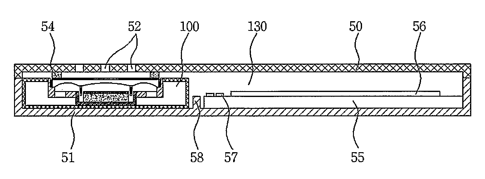
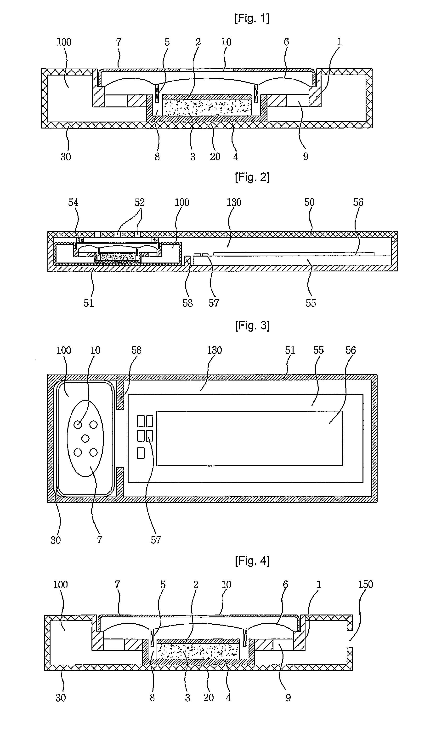
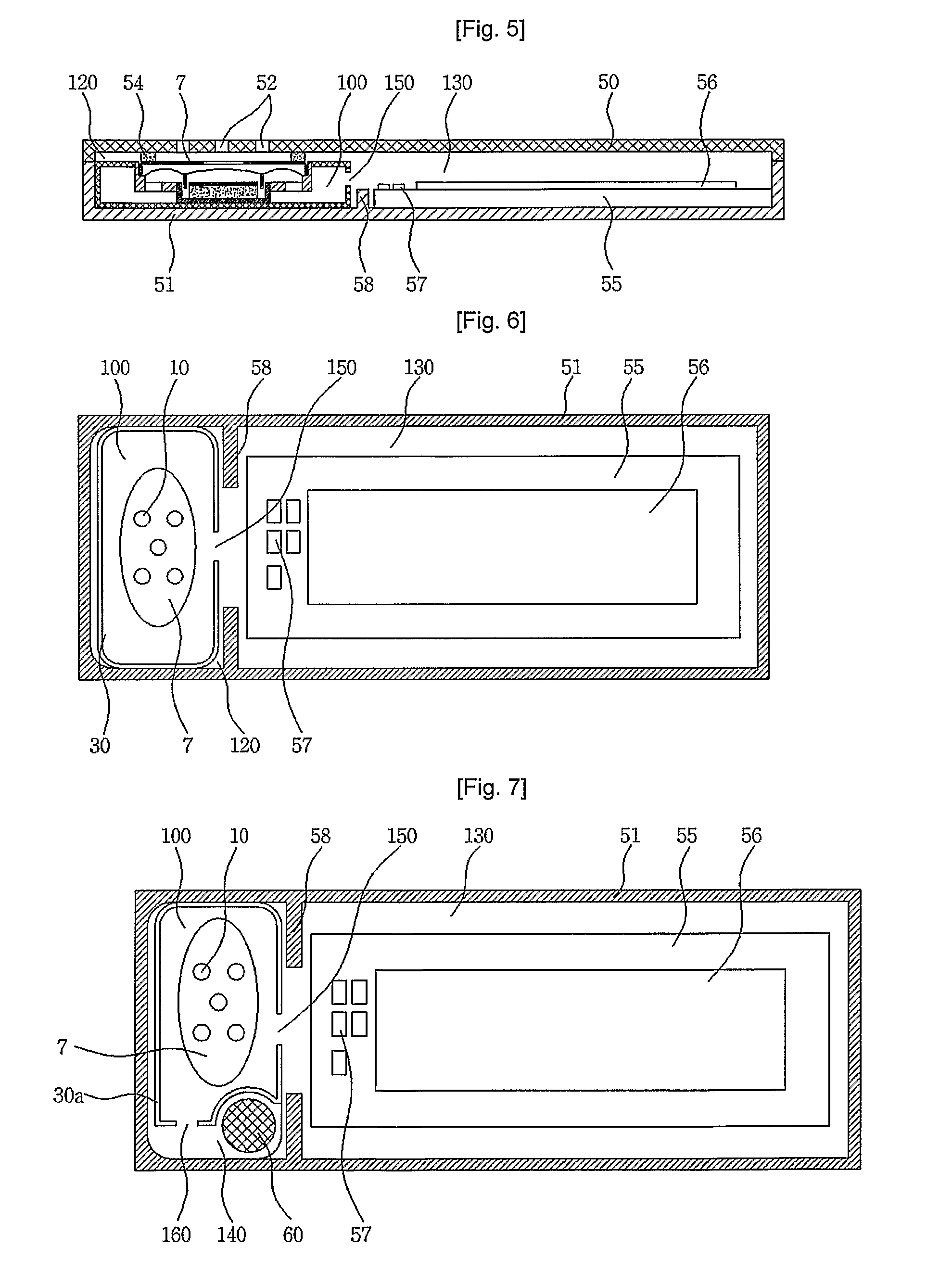
[0030]FIG. 4 is a cross-sectional view illustrating a sound converter with an enclosure in accordance with the present invention, and FIGS. 5 and 6 are cross-sectional views illustrating states where the sound converter with the enclosure according to the present invention is mounted in a mobile communication terminal.

[0031]Referring to FIG. 4, the sound converter with the enclosure according to the present invention includes a frame 1 on which a yoke 4, a magnet 3 and a top plate 2 are successively assembled, a voice coil 5 positioned in a gap 8 formed between the yoke 4 and the magnet 3, a diaphragm 6 adhered to the voice coil 5 and inserted into a diaphragm seating portion of the frame 1 to be vibratable, upper sound emitting holes 10 formed at the upper portion of the diaphragm 6, lower sound emitting ...


PUM


Abstract

The present invention discloses a sound converter with an enclosure which utilizes an outer space to expand a resonance space. The sound converter with the enclosure includes a frame being equipped with a magnetic circuit for forming a magnetic field in a predetermined gap, a voice coil at least partially positioned in the gap, a diaphragm adhered to the voice coil and inserted into a diaphragm seating portion of the frame, a protector formed at the upper portion of the diaphragm, and an enclosure case coupled to the frame, for defining the inner space of the enclosure which is the resonance space. A vent is provided at the enclosure case so that the inner space of the enclosure can communicate with the outer space. This configuration can secure a wide resonance space.

Description

TECHNICAL FIELD[0001]The present invention relates to a sound converter with an enclosure, and more particularly, to a sound converter with an enclosure which utilizes an outer space to expand a resonance space.BACKGROUND ART[0002]In general, a sound converter for converting an electric signal into a sound signal is installed in a portable communication terminal.[0003]FIG. 1 is a cross-sectional view illustrating a conventional sound converter with an enclosure, and FIGS. 2 and 3 are cross-sectional views illustrating states where the conventional sound converter with the enclosure is mounted in a portable terminal.[0004]The conventional sound converter with the enclosure includes a lower case 20 injection-molded with a synthetic resin in a predetermined shape, a yoke 4, a magnet 3 and a top plate 2 successively seated on a seating portion of the lower case 20, a diaphragm 6, a voice coil 5 fixed to the bottom surface of the diaphragm 6, a protector 7 formed at the upper portion of ...

Claims


Application Information

Patent Timeline
IPC IPC(8): H04R1/02
CPCH04M1/035H04R2499/11H04R1/2873H04B1/38H04R1/02
Inventor JEONG, SEUNG-KIUKIM, CHEON-MYEONGLEE, DONG-KYU
Owner EM TECHNOLOGY CO LTD
Why Eureka
Try Eureka