Method of manufacturing a thin-film magnetic head slider

Inactive Publication Date: 2006-09-28
FUJITSU LTD
View PDF8 Cites 0 Cited by
  • Summary
  • Abstract
  • Description
  • Claims
  • Application Information

AI Technical Summary

Benefits of technology

[0020] The entire lapping process on the row bar may be carried out using a single lapping device so that the lapping process can be carried out efficiently.
[0021] With the method of manufacturing a thin-film magnetic head slider according to the present

Problems solved by technology

Due to the construction of a thin-film magnetic head slider, there are problems such as electrical short circuits easily occurring at the magnetic sensor parts and deterioration occurring in the output of the magnetic sensor parts due to damaged areas (positions where fine scratches have been formed by the lapping) and/or distorted parts being formed.
Howev

Method used


Image

  • Method of manufacturing a thin-film magnetic head slider
  • Method of manufacturing a thin-film magnetic head slider
  • Method of manufacturing a thin-film magnetic head slider

Examples


Embodiment Construction

[0028] Preferred embodiments of the present invention will now be described in detail with reference to the attached drawings.

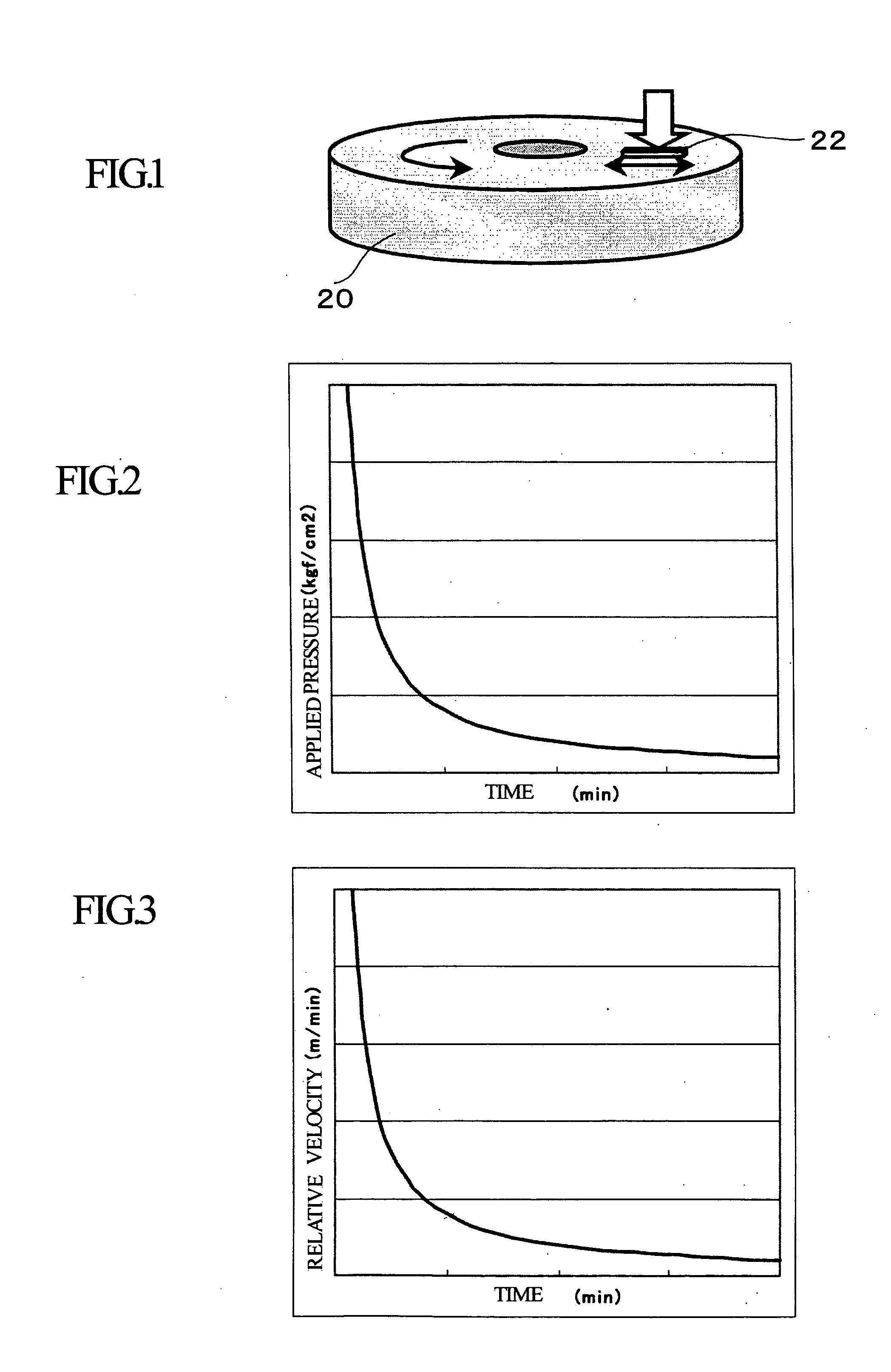
[0029] The method of manufacturing a thin-film magnetic head slider according to the present invention is characterized in that when an end surface of a row bar, which has been cut out in a strip from a wafer substrate on which magnetic sensor parts have been formed, is lapped, the lapping process is carried out while conditions (relative velocity and applied pressure) are changed either in accordance with stages in the lapping process or continuously as the lapping process proceeds.

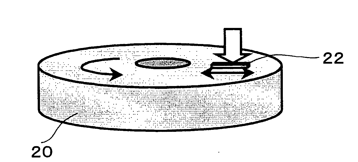
[0030]FIG. 1 shows a state where a row bar as a workpiece 22 is pressed onto a lapping plate 20 and lapped. When the lapping process is carried out on the workpiece 22 using the lapping plate 20, as shown in FIG. 1, the lapping plate 20 is rotated in one direction and the workpiece 22 is pressed onto a lapping surface of the lapping plate 20 with a predetermined pressure and als...


PUM

PropertyMeasurementUnit
Pressureaaaaaaaaaa
Velocityaaaaaaaaaa
Processing propertiesaaaaaaaaaa

Abstract

A method of manufacturing a thin-film magnetic head slider suppresses the production of damaged areas during lapping, reduces the lapping time, produces high-quality products, and is suited to mass production. The method of manufacturing a thin-film magnetic head slider laps an end surface of a row bar, which has been produced by cutting a wafer substrate on which magnetic sensor parts have been formed into strips, to expose an end surface of magnetic sensor parts to a floating surface, wherein a high processing rate is set in an initial part of a lapping process that laps the row bar and a lower processing rate is set in a later part of the lapping process.

Description

BACKGROUND OF THE INVENTION [0001] 1. Field of the Invention [0002] The present invention relates to a method of manufacturing a thin-film magnetic head slider, and in particular to a method of manufacturing a thin-film magnetic head slider characterized by a lapping method used on a floating surface of the thin-film magnetic head slider. [0003] 2. Related Art [0004] In the manufacturing process of a thin-film magnetic head slider, after magnetic sensor parts for reading and writing have been formed on a wafer substrate, the wafer substrate is cut into strips in accordance with the arrangement of elements formed on the wafer substrate and a lapping process is then carried out on the end surfaces of a row bar of cut-out sliders. The process that laps the end surface of a row bar exposes the magnetic sensor parts to the floating surface, with the lapping also having an object of producing predetermined characteristics for the magnetic sensor parts. [0005]FIG. 4 is a diagram useful in ...

Claims


Application Information

Patent Timeline
IPC IPC(8): B24B7/30B24B51/00B24B37/07G11B5/31G11B5/39
CPCB24B37/048G11B5/102G11B5/187G11B5/3169
Inventor HASHIMOTO, HIROKI
Owner FUJITSU LTD
Why Eureka
Try Eureka