Method for Producing Three-Dimensional Shaped Product, and Three-Dimensional Shaped Product Obtained by the Method

Active Publication Date: 2022-03-31
MATSUURA MACHINERY
View PDF0 Cites 0 Cited by
  • Summary
  • Abstract
  • Description
  • Claims
  • Application Information

AI Technical Summary

Benefits of technology

[0019]In the three-dimensional shaped product according to the basic construction (1), the basic construction (2) and the basic construction (3), even if either the one side direction or the other side direction in which the laser beam or the electron beam (hereunder referred to as “beam”) is scanned is perpendicular to a sliding direction of the squeegee, since the squeegee slides over a line-shaped sintered layer molded in a direction crossing that direction, if a beam scanning direction and the sliding direction of the squeegee are perpendicular as in the invention of Patent Document 2, then it is possible to avoid molding for the sintered layer with fine irregularities in a transverse direction due to uneven pressing force by sliding of the squeegee as shown in FIG. 10(b), which is caused by differences in thickness of the metal powder layer.
[0020]Further, in the case of the basic construction (1), for each powder layer, the bonding is three-dimensional in a range with identical height where a l

Problems solved by technology

As one three-dimensional shaped product production method that requires the gas permeability, Patent Document 1, for example, describes creating gas channels by way of a vesicular structure, in other words, a porous structure, but strength of the resulting shaped product is low, because the gas channels composed of the porous structure are formed by lowering the density of a solidified material, and the channels through which gas circulates are undefined and non-linear, therefore making it impossible to avoid the disadvantage of a low

Method used


Image

  • Method for Producing Three-Dimensional Shaped Product, and Three-Dimensional Shaped Product Obtained by the Method
  • Method for Producing Three-Dimensional Shaped Product, and Three-Dimensional Shaped Product Obtained by the Method
  • Method for Producing Three-Dimensional Shaped Product, and Three-Dimensional Shaped Product Obtained by the Method

Examples


Example

EXAMPLE

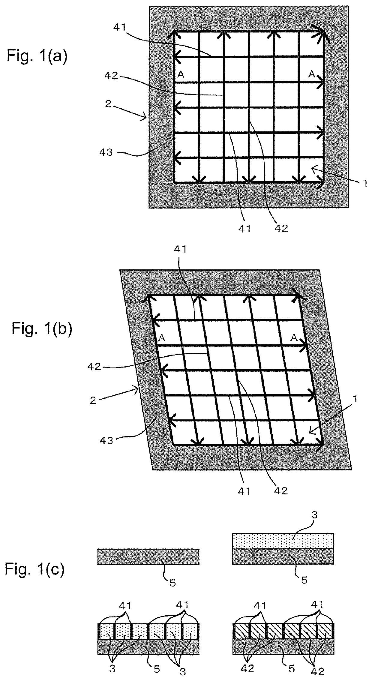
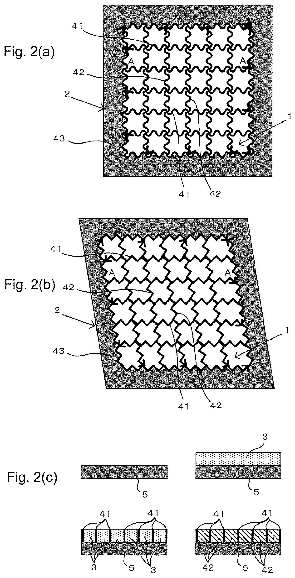
[0078]For molding in the lattice region 1, tubing for degassing is often situated below, which results in a base plate 5 being set only below the region where molding of the outer frame region 2 is expected to take place, as shown in FIG. 9, and molding of the lattice region 1 is often carried out without setting the base plate 5 below the region where molding of the lattice region 1 is expected to take place.

[0079]In such cases, it is essential for molding of the lattice region 1 to be carried out sequentially inward from the surrounding outer frame region 2.

Example

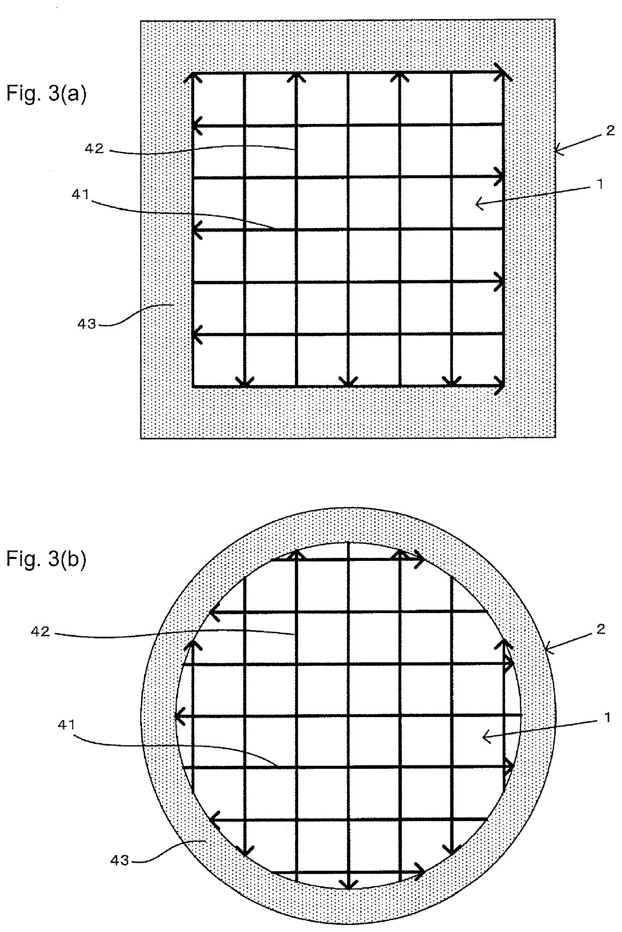
[0080]For Example 1, the lattice region 1 to be molded by sintering with scanning of the beam in the lattice region 1 along the one side direction and the other side direction is surrounded by a gap on an inner side, as shown in FIG. 9, with the size of the gap being sequentially decreased as layering progresses, so that molding of the lattice region 1 is carried out in a tapered form toward the inner side.

[0081]Employing such a tapered form allows the lattice region 1 to have the necessary width in the transverse direction, and also a predetermined strength.

INDUSTRIAL APPLICABILITY

[0082]The present invention is revolutionary in that it allows a lattice structure to be obtained with firm bonding and a uniform shape, and it widens potential range of use of three-dimensional shaping with a lattice structure.

REFERENCE SIGNS LIST

[0083]1: Lattice region[0084]11: Open pore[0085]12: Tapered region[0086]2: Outer frame region[0087]3: Powder layer[0088]41: Sintered layer in one side direction...


PUM

PropertyMeasurementUnit
Angleaaaaaaaaaa
Angleaaaaaaaaaa
Diameteraaaaaaaaaa

Abstract

A method for producing a three-dimensional shaped product based on repetition of a step of molding of a powder layer 3 and sintering with a laser beam or an electron beam, wherein in a lattice region 1, a sintered layer 41 is molded by scanning the beam having a predetermined spot diameter several times in one side direction at a predetermined interval, after which a sintered layer 42 is again molded by the same scanning in the other side direction which crosses the one side direction, and in an outer frame region 2, a continuous sintered layer 43 is molded by scanning the beam having the predetermined spot diameter over the entire lattice region 1 that is surrounded by an inner line and an outer line, and is also achieved by a three-dimensional shaped product obtained by the method.

Description

TECHNICAL FIELD[0001]The present invention relates to a method for producing a three-dimensional shaped product, targeting a surrounding outer frame and a lattice structure on an inner side after having established layering based on sequential repetition of a step of molding a powder layer by dispersion of powder while sliding a squeegee and sintering the powder layer using a laser beam or an electron beam, as well as to a three-dimensional shaped product obtained by the method.BACKGROUND ART[0002]Methods for producing three-dimensional shaped products are known wherein layering is established based on sequential repetition of a step of molding a powder layer by dispersion of powder while sliding a squeegee and sintering the powder layer using a laser beam or an electron beam.[0003]For many three-dimensional shaped products formed by such methods for producing the three-dimensional shaped products, the interior of the shaped product must often have gas permeability, i.e. a degassing...

Claims


Application Information

Patent Timeline
IPC IPC(8): B29C64/153B29C64/268B29C64/205
CPCB29C64/153B33Y10/00B29C64/205B29C64/268Y02P10/25B22F5/10B22F3/1103B33Y80/00B33Y50/02B22F10/366B22F10/28B22F10/38B22F10/85B01D39/1661B01D39/2034B22F2999/00B22F3/14B22F12/53B22F12/84B33Y30/00
Inventor AMAYA, KOICHITETSUSHI, MIDORIKAWATOMITA, SEIICHITANAKA, RYUZO
Owner MATSUURA MACHINERY
Why Eureka
Try Eureka