
Multi-cylinder internal combustion engine with independent cylinders
- Summary
- Abstract
- Description
- Claims
- Application Information
AI Technical Summary
Benefits of technology
Problems solved by technology
Method used
Image

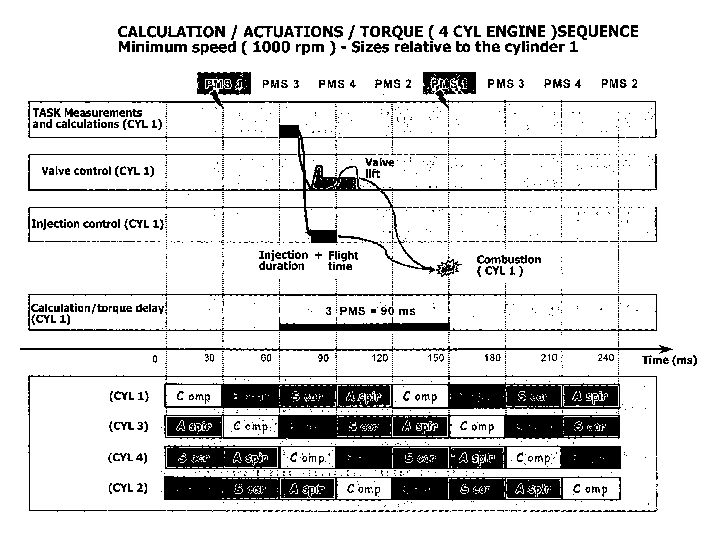
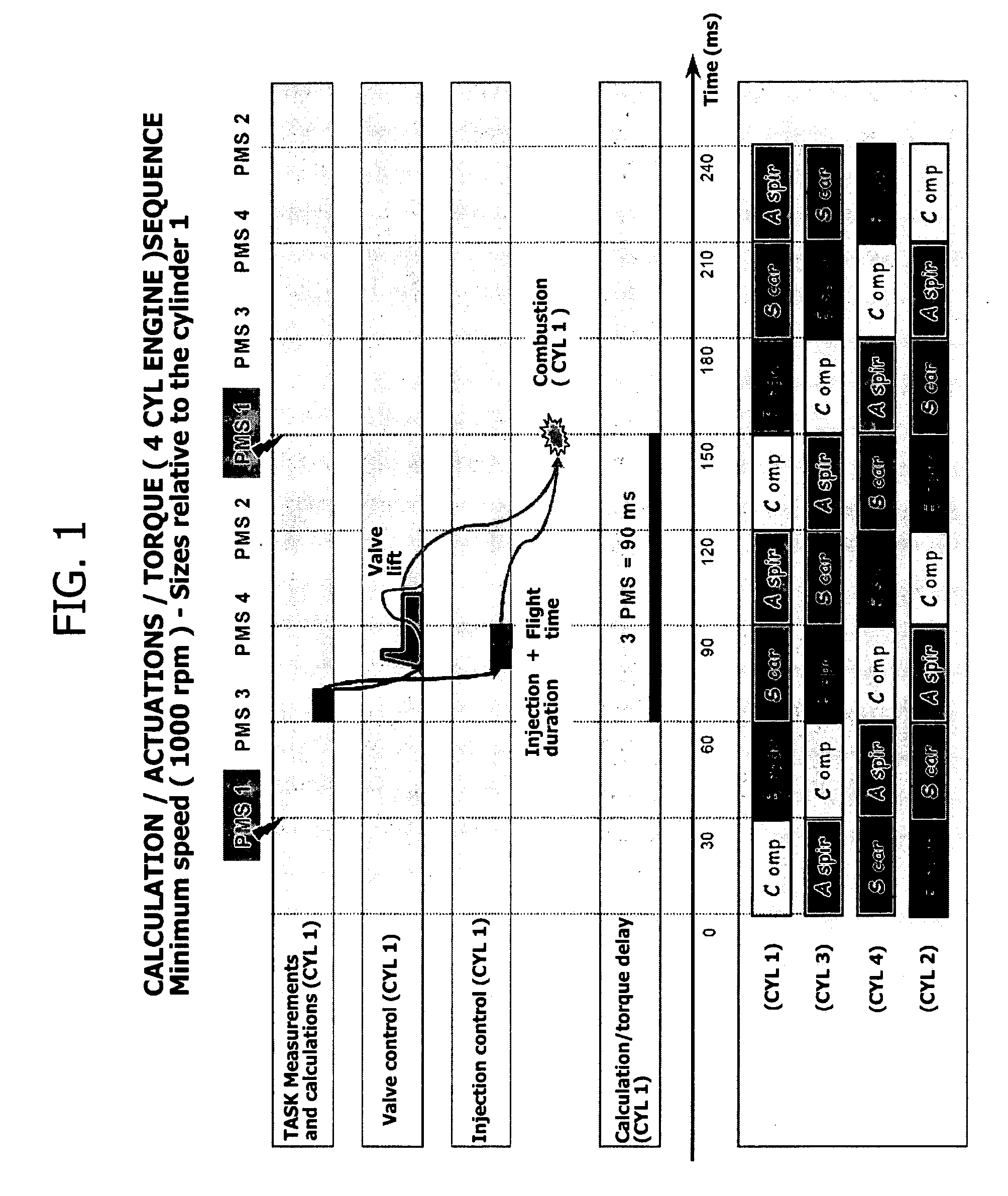
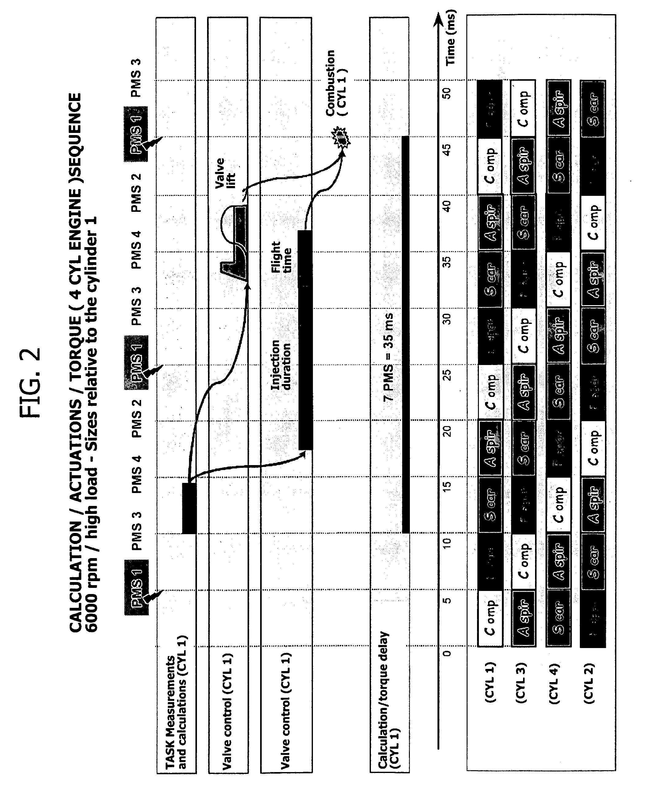
Examples
Embodiment Construction
[0030]The present invention refers to internal combustion engines that provide actuator means adapted to control the intake valve of each cylinder independently from the other cylinders and according to a variable actuation mode.
[0031]An internal combustion engine of this type is, for example, represented by the internal combustion engines provided by the variable operating system of the valves which is schematically depicted in FIG. 4, and which is the subject matter of several patents by the same Applicant.
[0032]With reference to FIG. 4, the reference numeral 1 designates the valve as a whole (which can be either a intake valve or an exhaust valve) associated with a respective pipe 2 (suction or exhaust) formed in an internal combustion engine head 3. The valve 1 is returned towards its closed position (upwards with reference to FIG. 4) by a spring 4, whilst this is forced to open by a piston 5 acting on the upper end of the valve stem. The piston 5 is, in turn, controlled through...
PUM
 Abstract
Description
Claims
Application Information