Combustion apparatus

Inactive Publication Date: 2010-09-30
DAINICHI +1
View PDF50 Cites 2 Cited by
  • Summary
  • Abstract
  • Description
  • Claims
  • Application Information

AI Technical Summary

Benefits of technology

[0016]By configuring the combustion apparatus as described above, the liquid fuel can be provided with adequate time

Problems solved by technology

In other words, if time required for evaporating the liquid fuel is not provided when the

Method used


Image

  • Combustion apparatus
  • Combustion apparatus
  • Combustion apparatus

Examples


Example

[0019]Embodiments of the present invention, which are considered preferable, are now described simply by illustrating the functions of the present invention.

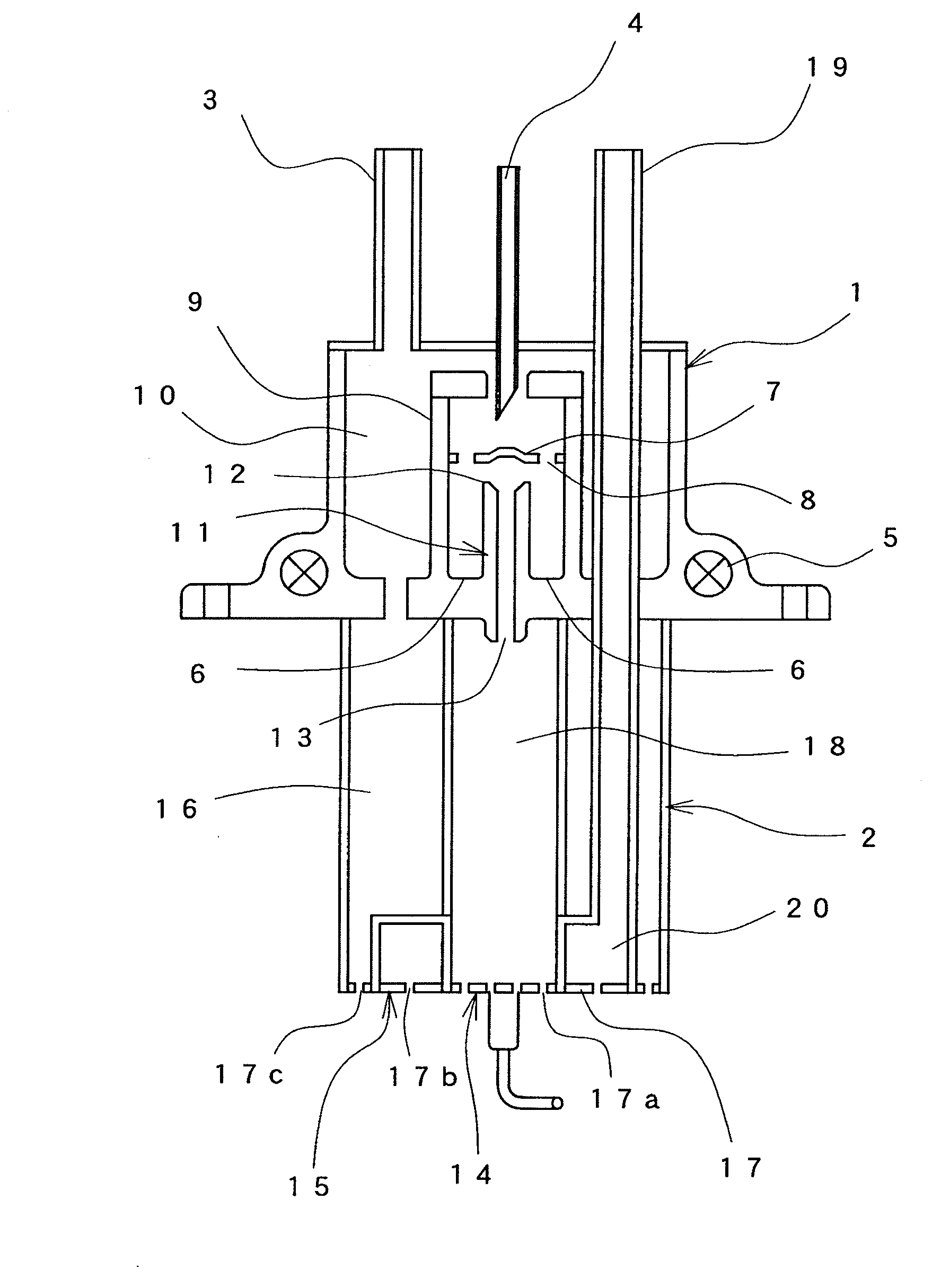
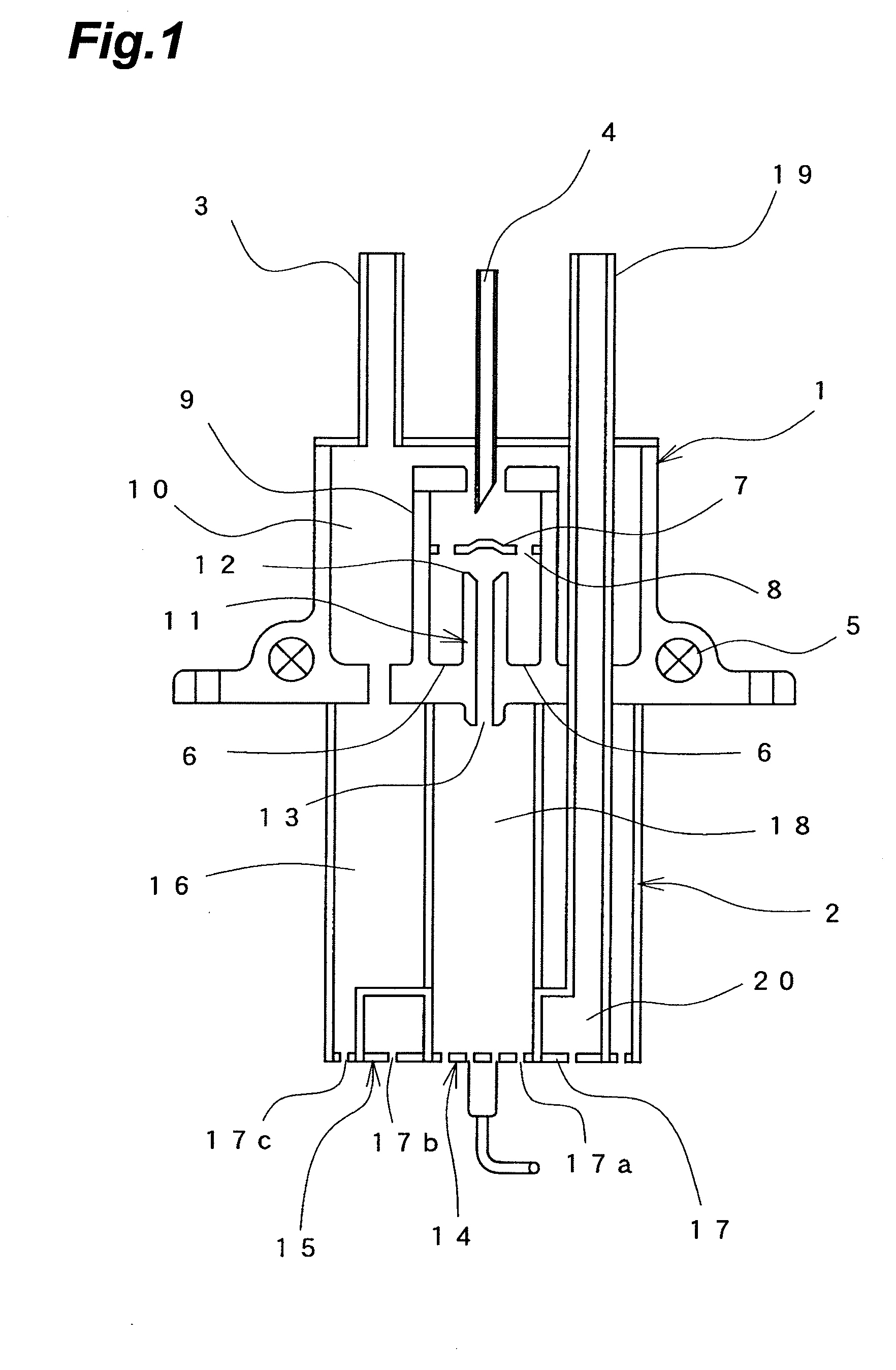
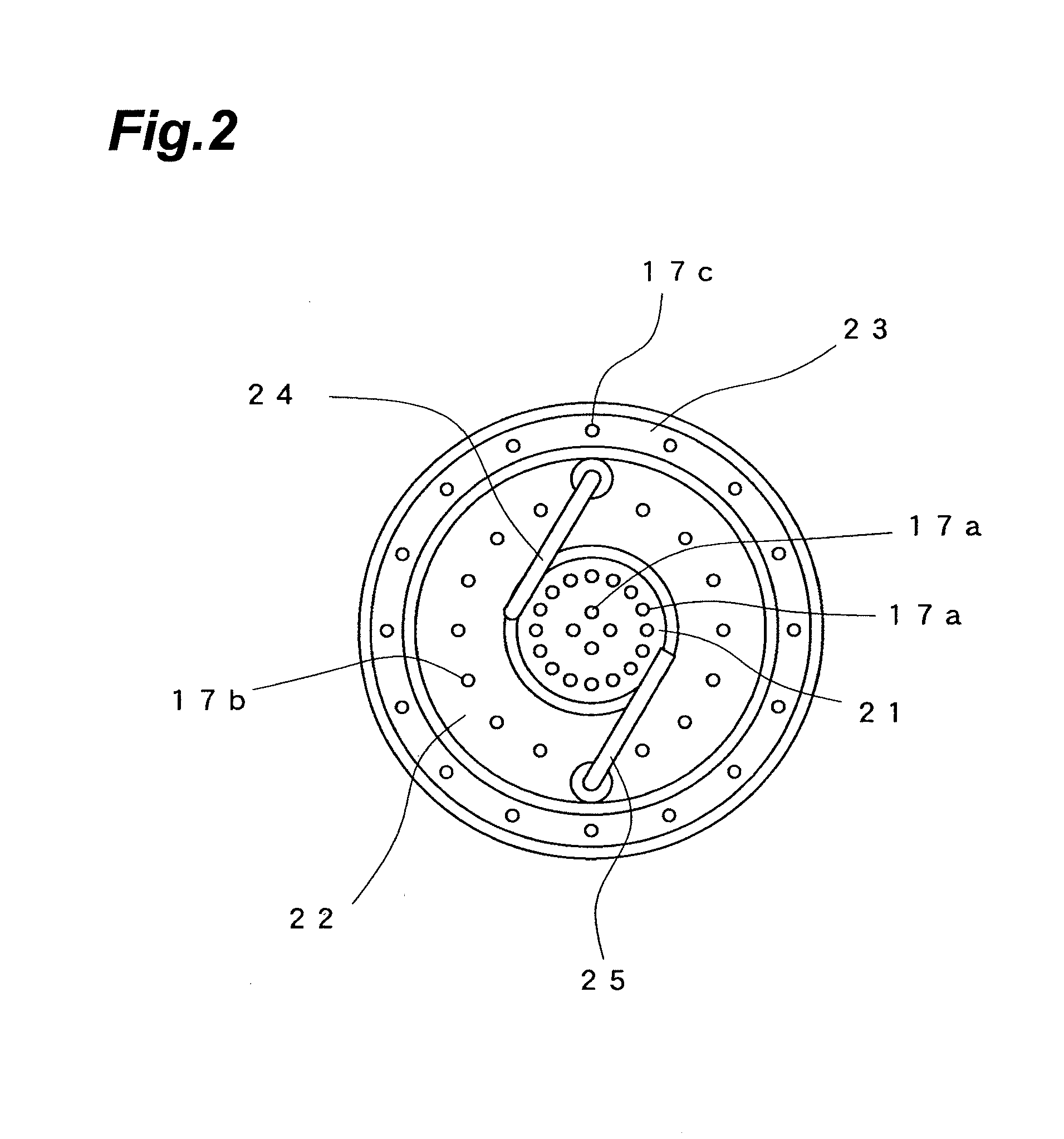
[0020]The present invention is a combustion apparatus, which has a vaporizer for generating premixed gas of combustion gas vaporized from liquid fuel and primary air, and combusts this premixed gas using a burner part provided vertically below the vaporizer.

[0021]Specifically, the liquid fuel supplied to the vaporizer is heated and thereby vaporized into combustion gas by an evaporating part. This combustion gas is mixed with the primary air by a vaporizing chamber to obtain the premixed gas. Thereafter, the premixed gas flows from an inflow port into a premixed gas spout part and is spouted out of a spout port toward the burner part.

[0022]Because the inflow port of the premixed gas spout part is provided at a position higher than the evaporating part, a space serving as a tray for receiving the liquid fuel is formed between the...


PUM


Abstract

To provide a combustion apparatus that has a vaporizer capable of vaporizing liquid fuel completely without complicating the structure of the combustion apparatus. The combustion apparatus has an evaporating part for heating and vaporizing the liquid fuel into combustion gas, and a premixed gas spout part for spouting out premixed gas in which the combustion gas is mixed with primary air, with an inflow port of the premixed gas spout part being provided at a position higher than the evaporating part. By configuring the combustion apparatus like this, a space for accumulating unvaporized liquid fuel is formed between the evaporating part and the inflow port, and sufficient time to completely vaporize the liquid fuel can be afforded. Therefore, unevaporated fuel in a liquid state can be prevented from flowing into the premixed gas spout part.

Description

BACKGROUND OF THE INVENTION[0001]1. Field of the Invention[0002]The present invention relates to a combustion apparatus for combusting premixed gas of combustion gas vaporized from liquid fuel and primary air.[0003]2. Related Background Art[0004]There has been conventionally known a combustion apparatus that has a vaporizer heated by a heater, supplied with liquid fuel, and generating combustion gas by heating and vaporizing the liquid fuel. The generated combustion gas is mixed with primary air to obtain premixed gas, which is then spouted out from a burner and combusted.[0005]In such a combustion apparatus, if the liquid fuel is not vaporized sufficiently in the vaporizer, the liquid fuel that is not completely vaporized is deposited in the form of tar, causing poor vaporization, or the fuel reaches the burner directly as liquid, causing poor combustion. For this reason, various improvements have been made in order to vaporize the liquid fuel completely.[0006]For example, Japanese...

Claims


Application Information

Patent Timeline
IPC IPC(8): F23D11/44
CPCF23D5/04F23D14/62F23D5/16F23D5/045
Inventor EHARA, HIROYUKIGOTO, AKIRA
Owner DAINICHI
Why Eureka
Try Eureka