Apparatus and process for regenerating catalyst

Inactive Publication Date: 2006-04-11
UOP LLC
View PDF18 Cites 72 Cited by
  • Summary
  • Abstract
  • Description
  • Claims
  • Application Information

AI Technical Summary

Benefits of technology

[0014]This invention is directed to an arrangement for removing carbon deposits referred to as coke from the surface and pores of catalyst used in a hydrocarbon conversion process. Hybrid turbulent bed and fast fluidized conditions in a regeneration vessel assure adequate residence time for regenerating spent hydrocarbon cracking catalyst. The combustion chamber u

Problems solved by technology

Hence, unless the combustion chamber of a combustor vessel is enlarged, the residence time of catalyst in the lower zone will dimin

Method used


Image

  • Apparatus and process for regenerating catalyst
  • Apparatus and process for regenerating catalyst
  • Apparatus and process for regenerating catalyst

Examples


Embodiment Construction

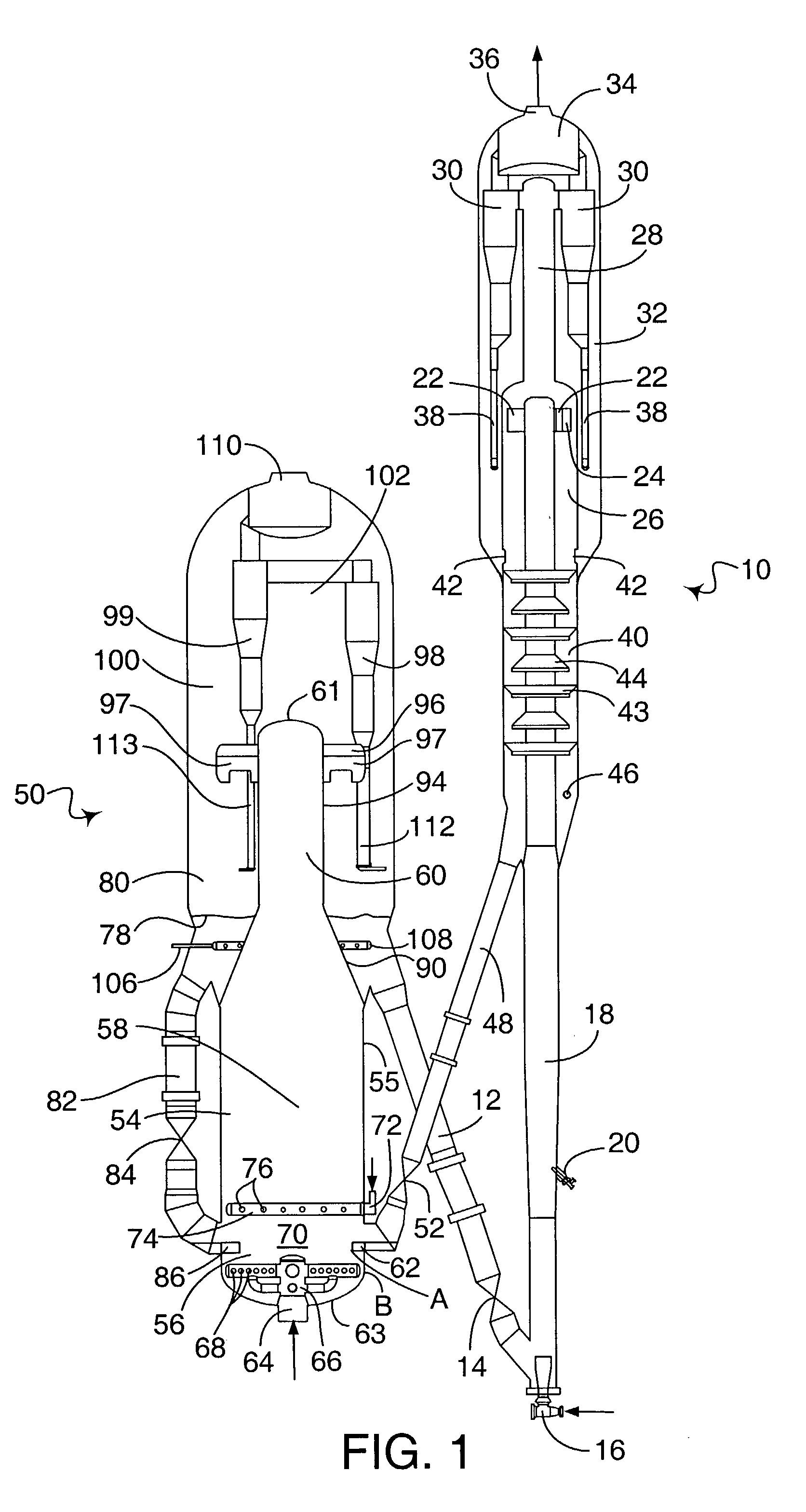
[0017]The process and apparatus of the present invention may be embodied in an FCC unit. FIG. 1 shows an FCC unit that includes a reactor vessel 10 and a combustor vessel 50. A combustor standpipe 12 transfers catalyst from the combustor vessel 50 at a rate regulated by a slide valve 14 to the reactor vessel 10. A fluidization medium such as steam from a nozzle 16 transports catalyst upwardly through a riser 18 at a relatively high density until a plurality of feed injection nozzles 20 (only one is shown) inject feed across the flowing stream of catalyst particles. The resulting mixture continues upwardly through the riser 18 until a pair of disengaging arms 22 tangentially discharge the mixture of gas and catalyst from a top of the riser 18 through ports 24 into a disengaging vessel 26 that effects separation of gases from the catalyst. A transport conduit 28 carries the hydrocarbon vapors, including stripped hydrocarbons, stripping media and entrained catalyst to one or more cyclo...


PUM

PropertyMeasurementUnit
Speedaaaaaaaaaa
Speedaaaaaaaaaa
Residence timeaaaaaaaaaa

Abstract

Disclosed is an apparatus and process for prolonging the residence time of catalyst in a chamber for regenerating catalyst. Spent catalyst, perhaps from an FCC reactor, is introduced into a chamber of a regeneration vessel between lower and higher combustion gas distributors. The velocity of gas from the lower distributor is insufficient to entrain catalyst from the bed, and gas from the higher distributor when combined with gas rising from the lower distributor is sufficient to generate a fast fluidized flow condition. The second distributor elevates the location of the transition from turbulent bed to fast fluidized conditions.

Description

BACKGROUND OF THE INVENTION[0001]The invention relates to a method of regenerating spent hydrocarbon conversion catalyst by the combustion of coke on the catalyst in a fluidized combustion zone. This invention specifically relates to a process for the conversion of heavy hydrocarbons into lighter hydrocarbons with a fluidized stream of catalyst particles and regeneration of the catalyst particles to remove coke that acts to deactivate the catalyst.[0002]Fluidized catalytic cracking (FCC) is a hydrocarbon conversion process accomplished by contacting hydrocarbons in a fluidized reaction zone with a catalyst composed of finely divided particulate material. The reaction in catalytic cracking, as opposed to hydrocracking, is carried out in the absence of added hydrogen or the consumption of hydrogen. As the cracking reaction proceeds substantial amounts of highly carbonaceous material referred to as coke is deposited on the catalyst. A high temperature regeneration within a regeneration...

Claims


Application Information

Patent Timeline
IPC IPC(8): B01J20/34B01J38/12B01J38/30B01J38/36
CPCB01J38/30F27B15/00C10G11/182B01J38/34B01J38/02
Inventor PALMAS, PAOLOLOMAS, DAVID A.
Owner UOP LLC
Why Eureka
Try Eureka