
High-voltage electrical connector

a high-voltage electrical connector and connector technology, applied in the direction of electrically conductive connections, coupling device connections, transformer/inductance cooling, etc., can solve the problems of leakage, consequently reducing the risk of leakage between the first chamber and the surrounding environmen

Inactive Publication Date: 2010-09-30
VETCO GRAY SCANDINAVIA
View PDF11 Cites 0 Cited by
  • Summary
  • Abstract
  • Description
  • Claims
  • Application Information

AI Technical Summary

Benefits of technology

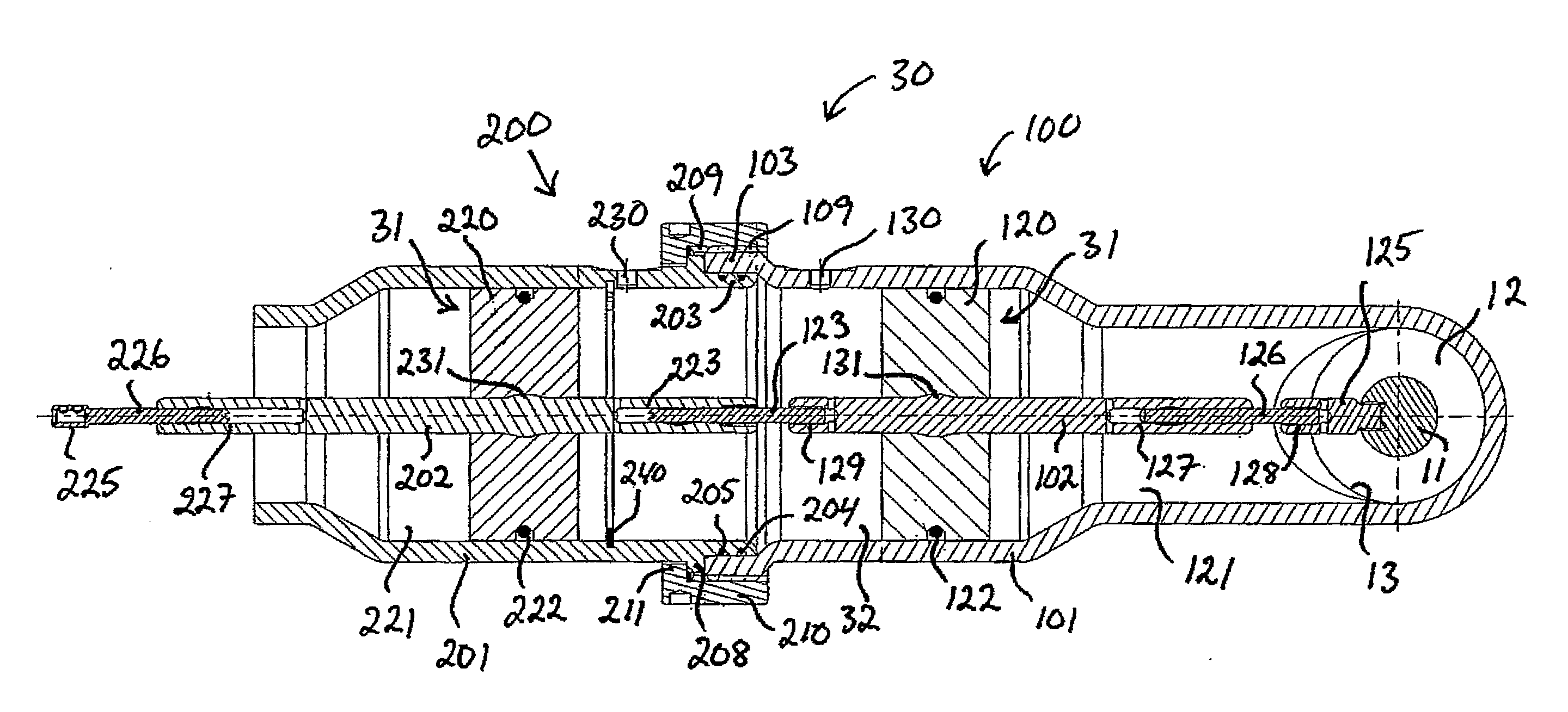
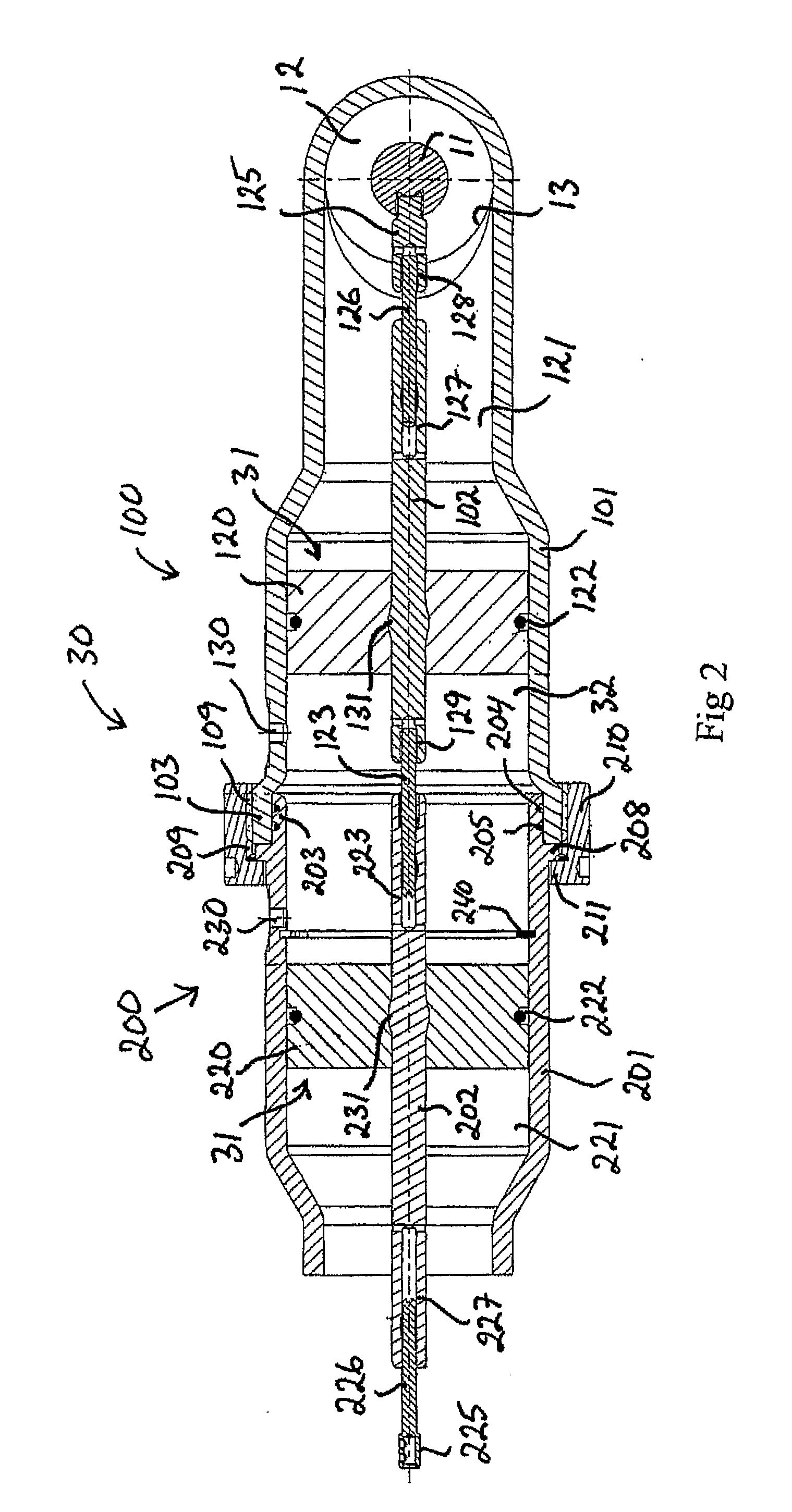
[0007]According to the inventive solution, a volume compensating arrangement is integrated in a high-voltage electrical connector designed to electrically connect a first electrical appliance located in a fluid-filled first chamber to a second electrical appliance located in a fluid-filled second chamber. The volume compensating arrangement of the high-voltage electrical connector is designed to allow said first chamber to be volume compensated to said second chamber via the high-voltage electrical connector. Thus, the first chamber can be volume compensated without requiring any separate volume compensator of conventional and normally rather bulky type. Hereby, the overall size of the electrical assembly comprising said first and second electrical appliances may be reduced. Furthermore, there is a risk that a leakage may arise in a conventional volume compensator and the risk of leakage between the first chamber and the surroundings is consequently reduced by dispensing with such a separate volume compensator for the first chamber.
[0009]According to an embodiment of the high-voltage electrical connector of the present invention, the volume compensating arrangement of the electrical connector comprises one or several piston members for keeping the fluid in the first chamber separated from the fluid in the second chamber, said one or several piston members being displaceable under the effect of variations of the volume of the fluid in the first chamber so as to thereby allow such volume variations to be taken up by the fluid in the second chamber. Hereby, the first chamber is volume compensated to the second chamber in a simple and efficient manner.
[0015]This design of the electrical connector with two mutually connectable casings and a separate piston member in each casing will offer advantages with respect to the operation of connecting two electrical appliances of an electrical assembly by means of the electrical connector in question. These advantages will appear from the detailed description below.

Problems solved by technology

Furthermore, there is a risk that a leakage may arise in a conventional volume compensator and the risk of leakage between the first chamber and the surroundings is consequently reduced by dispensing with such a separate volume compensator for the first chamber.

Method used


Image

  • High-voltage electrical connector
  • High-voltage electrical connector
  • High-voltage electrical connector

Examples


Embodiment Construction

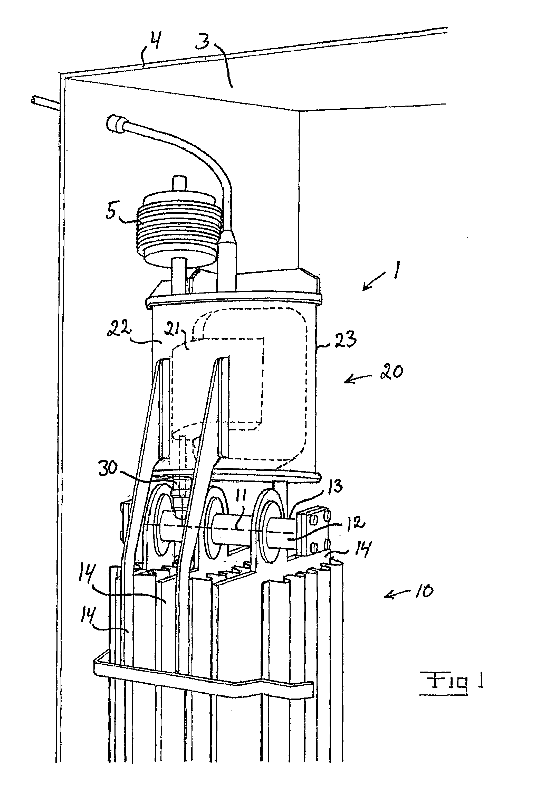
[0023]A part of an electrical assembly 1 provided with an electrical connector 30 according to the present invention is illustrated in FIG. 1. The electrical assembly 1 comprises a first electrical appliance 11 located in a fluid-filled first chamber 12 and a second electrical appliance 21 located in a fluid-filled second chamber 22.

[0024]In the illustrated embodiment, the electrical assembly 1 comprises an electrostatic coalescing device 10 and a power supply unit 20 for supplying electric power to a number of sheet-shaped electrodes 14 of the electrostatic coalescing device. In this case:[0025]the above-mentioned second electrical appliance 21 is a high-voltage transformer (illustrated in broken lines in FIG. 1) forming part of the power supply unit 20;[0026]the above-mentioned second chamber 22 is the internal space of a transformer housing 23 accommodating the transformer 21;[0027]the above-mentioned first electrical appliance 11 is a conductor (represented by a broken line in F...


PUM


Abstract

A method for volume compensation of a fluid-filled first chamber accommodating a first electrical appliance that is electrically connected by a high-voltage electrical connector to a second electrical appliance located in a fluid-filled second chamber. The first chamber is volume compensated to the second chamber via the electrical connector by a volume compensating arrangement integrated in the electrical connector. A high-voltage electrical connector with a volume compensating arrangement and an electrical assembly provided with such a connector.

Description

FIELD OF THE INVENTION AND PRIOR ART[0001]The present invention relates to a method for volume compensation of a fluid-filled first chamber provided with a first electrical appliance that is electrically connected by means of a high-voltage electrical connector to a second electrical appliance located in a fluid-filled second chamber. The invention also relates to a high-voltage electrical connector according to the preamble of claim 3 and an electrical assembly according to the preamble of claim 14.[0002]In the oil and gas industry where oil is extracted from one or more wells in an oil field, oil will be extracted together with water. The water has to be removed from the oil and this is mainly done by means of settling tanks in which the oil is permitted to settle under the action of gravity. However, stable oil-water emulsions may develop during the production of the oil. For example, the use of gas-liquid cyclones might contribute to a stable emulsion that will be difficult to s...

Claims


Application Information

Patent Timeline
IPC IPC(8): H01R13/533
CPCH01F27/14H01R13/523H02G15/26H01R13/53
Inventor HAFSKJOLD, GUNNARAARBAKKE, SIGRID
Owner VETCO GRAY SCANDINAVIA
Learn More