Vented refuse can

Inactive Publication Date: 2010-10-07
CLEMENTS CARLOS
View PDF4 Cites 52 Cited by
  • Summary
  • Abstract
  • Description
  • Claims
  • Application Information

AI Technical Summary

Benefits of technology

[0003]The object of the present invention is to provide a ventilation system that will allow air trapped between the tra

Problems solved by technology

Numerous prior trash receptacles are adapted to hold trash bags, however when first inserted an

Method used


Image

  • Vented refuse can
  • Vented refuse can
  • Vented refuse can

Examples


Example

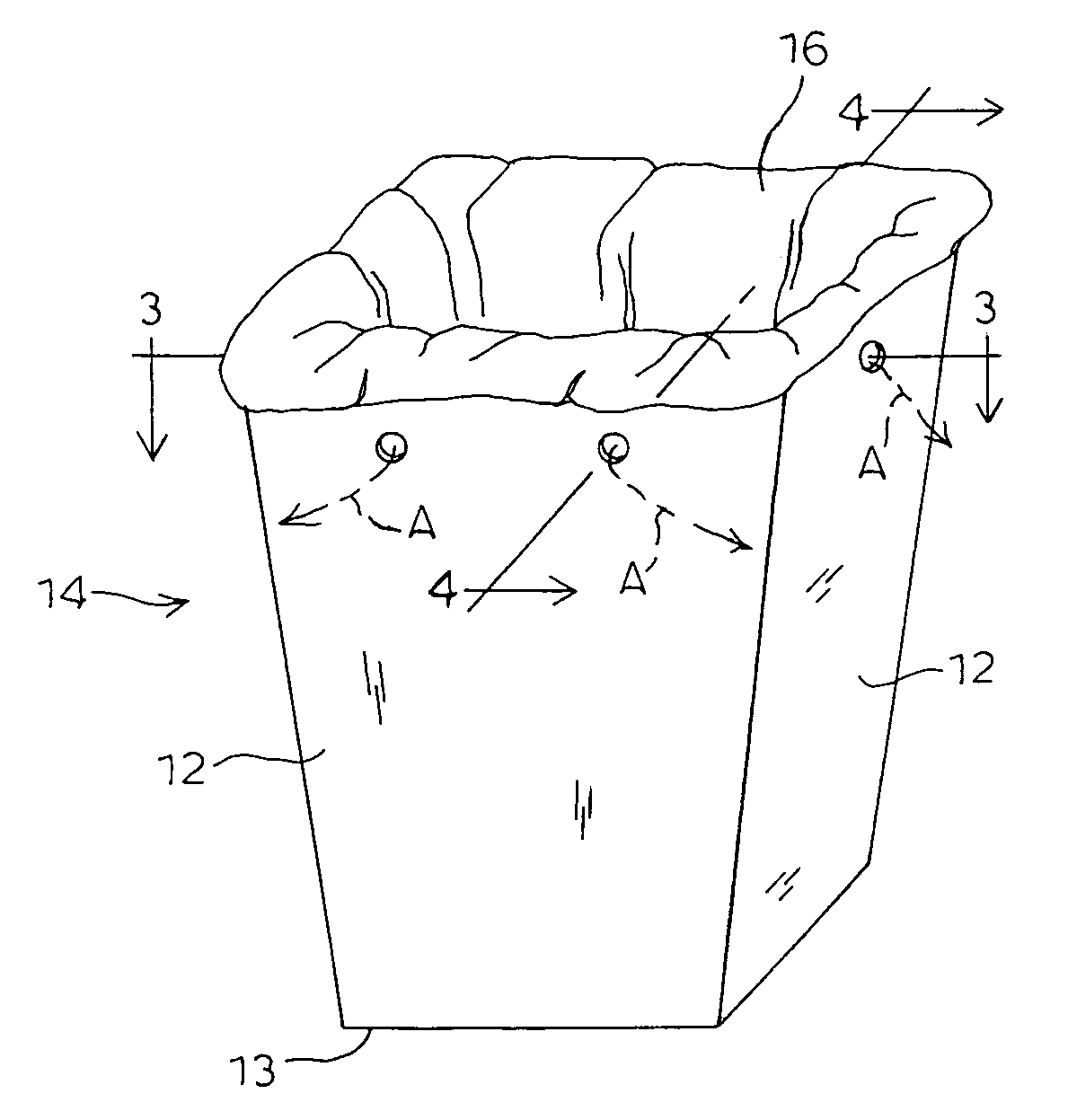
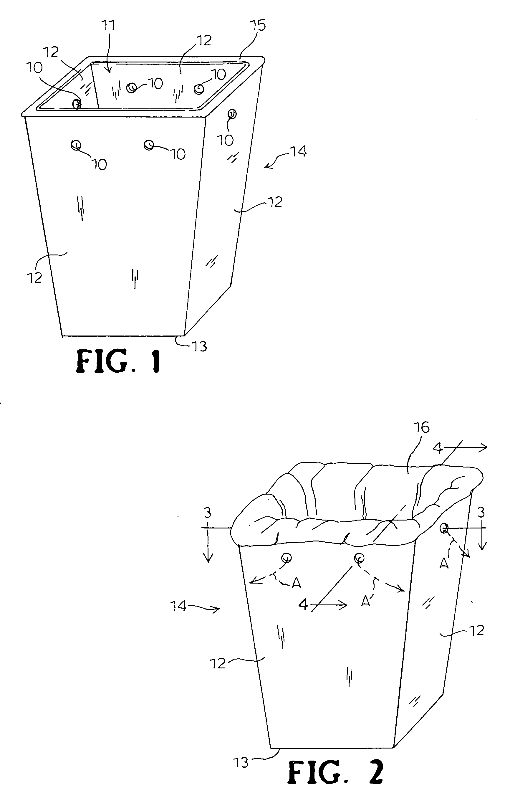
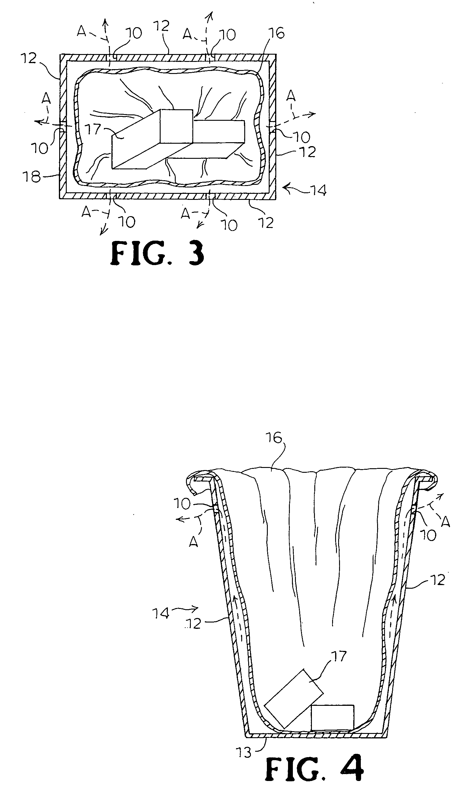
[0011]The invention description is as follows; The receptacle consists of sidewalls 12 and a bottom 13 with an open top 11, which creates the refuse can receptacle 14 named Vented Refuse Can 15. The openings in the upper portion of the sidewalls of the receptacle are called vents 10. These vents are located in the upper portion of the receptacle sidewalls 12 to optimize air A flow release when the trash bag 16 is inserted into the receptacle 14. Once the trash bag 16 is in place almost immediately the trapped air A begins to escape through the vents 10 immediately reducing the air A pressurized and trapped between the receptacle walls 12 and the trash bag 16. When trash 17 is tossed or inserted into the trash bag 16 in the receptacle 14 it increases the air pressure, which can cause the trash bag to rip or slip from the receptacle's rim. The vents 10 prevent this from happening by allowing the pressurized air A to escape slowly or quickly when trash 17 is inserted into the trash bag...


PUM


Abstract

The vented refuse can consist of a unique component accompanying the open top receptacle where trash bags are inserted and removed. The component that makes this present invention unique is the openings located in the upper part of the receptacle's sidewalls, which allow trapped air between the receptacle and the trash bag to be released. The trapped air being released will prevent bag tearing and slipping off the rim of the receptacle, which will reduce the number of wasted trash bags due to rips and holes caused by the trapped air when trash is tossed into the receptacle.

Description

BACKGROUND ON THE INVENTION[0001]The instant invention relates generally to garbage receptacles and more specifically relates to vented trash receptacles for a more stable and sturdy trash bag.[0002]Numerous prior trash receptacles are adapted to hold trash bags, however when first inserted and trash is tossed into the receptacle they rip or dislodge from the rim of the trash receptacle. These current trash receptacles are suitable for the purpose they address, they would not be suitable for the present invention as heretofore described.SUMMARY OF THE INVENTION[0003]The object of the present invention is to provide a ventilation system that will allow air trapped between the trash bag and the trash receptacle to be released, preventing trash bags tearing and slipping off the rim of the receptacle.[0004]Another object is to provide this invention in order to prevent trash bag damage making them unusable and or unsafe for trash collection and storage.[0005]An additional object of this...

Claims


Application Information

Patent Timeline
IPC IPC(8): B65D25/14B65D25/00
CPCB65F2210/1815B65F1/06
Inventor CLEMENTS, CARLOS
Owner CLEMENTS CARLOS
Why Eureka
Try Eureka