
Calibration method and apparatus for automotive camera system, and method and ecu for determining angular misalignments of automotive camera system

Inactive Publication Date: 2010-10-07
SAMSUNG ELECTRO MECHANICS CO LTD
View PDF12 Cites 46 Cited by
  • Summary
  • Abstract
  • Description
  • Claims
  • Application Information

AI Technical Summary

Benefits of technology

[0014]Accordingly, an advantage of the present invention is to provide the camera system calibration method that does not require attachment of any target apparatus to the body of the vehicle, is fast and inexpensive to be carried out both on the car assembly line and in the garage conditions.
[0015]According to the present invention the targets to be captured by the camera units are placed or painted on the ground in the peripheral area of the vehicle. The targets do not have to be placed precisely in any predefined position with respect to the vehicle.
[0016]Each camera unit captures the targets. Then, the vehicle is moved forward or backward, without moving the targets, and another image is captured. The vehicle may be moved on its own wheels (in this case steering wheel has to be in position ensuring motion of the vehicle along the longitudinal direction, without making a turn), on a conveyor, or any other mean. The targets are detected on both images and their coordinates on the corresponding images determined.
[0017]By calculating world coordinates of the targets before and after the displacement of the vehicle from the captured images, and comparing them to each other, the angular misalignment of each camera is determined, and the image processing parameters are modified correspondingly for each camera unit.
[0018]The advantage of the present invention is that the calibration of the camera system does not require mechanical adjustment of camera units' orientation.
[0019]Another advantage of the present invention is that the targets to be captured do not have to be located precisely in the predetermined positions with respect to the vehicle, thus eliminating the need to install target apparatus on the vehicle.

Problems solved by technology

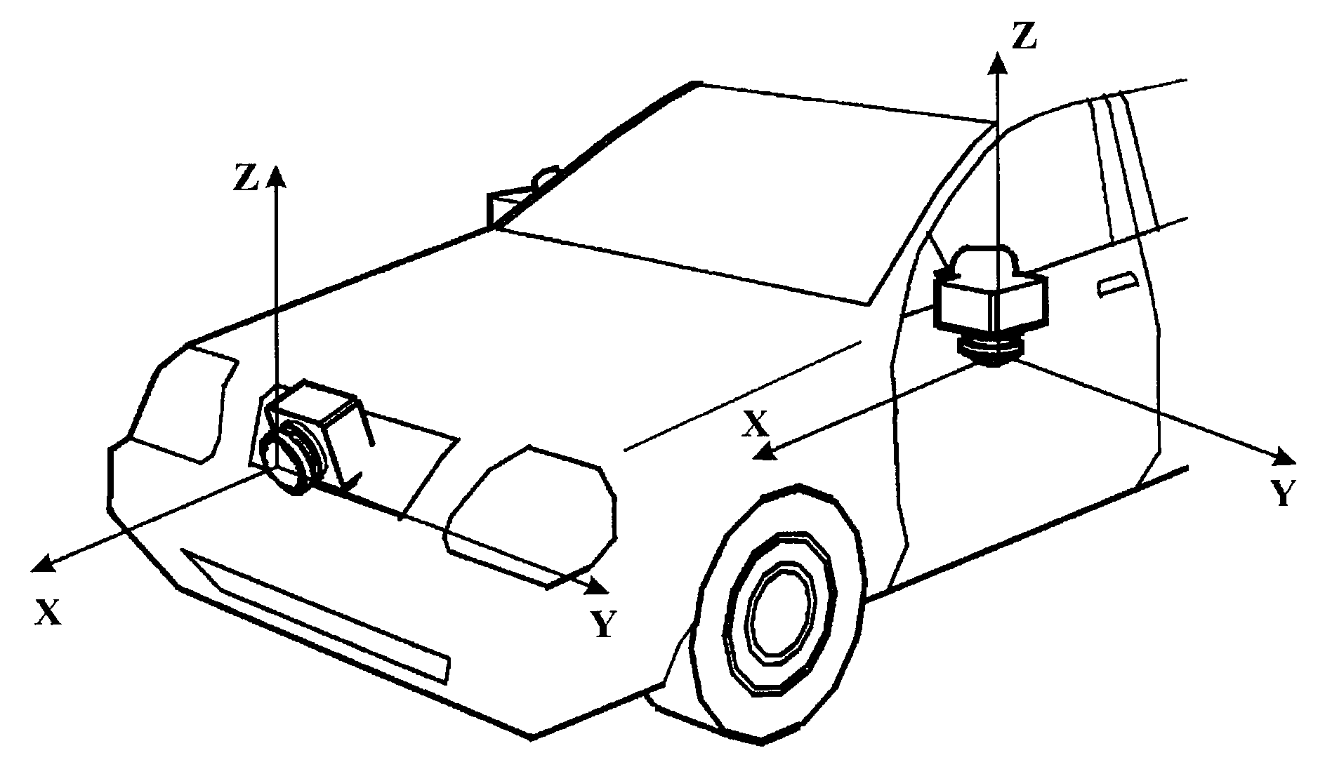
However if the cameras are misaligned with respect to the vehicle and each other, the displayed image may not only look unpleasant to a human eye, but also cause confusion and misinterpretation of the distance to the object and thus deteriorate safety. FIG. 4 shows an example of the resulting image in the case of FVC misalignment.
But this operation is too labor-intensive to be used on the car assembly line.
Failure in positioning the target properly results in erroneous camera orientation.
Therefore, when used in the garage, these methods require high qualification of the personnel, partial disassembly of the vehicle components, large space to arrange the targets, and long time to carry out, thus increasing the cost of car service.
Moreover, the adjustable fasteners that hold camera on place but also allow changing the orientation whenever the adjustment is made, are more complex and expensive that non-adjustable rigid brackets.
This method is also of limited use on the car assembly lines, because it requires installing the target apparatus on a vehicle, at least one for each camera included in the system.
On the other hand, in the garage conditions, the need for special equipment (target apparatus) to perform the calibration increases the cost of the service.
Also, the design of the vehicle has to be made taking into consideration the means to mount the target apparatus with the high precision, which imposes extra restrictions and requirements and may spoil the appearance of the vehicle.

Method used


Image

  • Calibration method and apparatus for automotive camera system, and method and ecu for determining angular misalignments of automotive camera system
  • Calibration method and apparatus for automotive camera system, and method and ecu for determining angular misalignments of automotive camera system
  • Calibration method and apparatus for automotive camera system, and method and ecu for determining angular misalignments of automotive camera system

Examples


Embodiment Construction

[0048]The present inventive concept will now be described more fully with reference to the accompanying drawings, in which exemplary embodiments of the invention are shown. The present inventive concept may, however, be embodied in many different forms and should not be construed as being limited to the embodiments set forth herein; rather, these embodiments are provided so that this disclosure will be thorough and complete, and will fully convey the concept of the invention to those skilled in the art. In the following description, well-known functions or constructions are not described in detail since they would obscure the invention in unnecessary detail.

[0049]Although terms like “first” and “second” are used to describe various elements, these elements are not limited to these terms. These terms are used only to differentiate one element from another.

[0050]Terms used herein are for the purpose of describing particular embodiments only and is not intended to be limiting of exempl...


PUM


Abstract

A method of automotive camera system calibration is disclosed in the present invention. At least two targets are placed within the field of view of each camera included in the system. Each camera captures the targets. Then, the vehicle is moved, and another image is captured. The images are used to derive the camera orientation parameters. Based on these parameters, misalignment of the cameras can be compensated by the image processing unit.

Description

CROSS-REFERENCE TO RELATED APPLICATIONS[0001]This application claims the benefit of Korean Patent Application No. 10-2009-0029342 filed with the Korea Intellectual Property Office on Apr. 6, 2009, the disclosure of which is incorporated herein by reference.BACKGROUND OF THE INVENTION[0002]1. Field of the Invention[0003]The present inventive concept relates to the camera system, comprising several image sensor based camera units, attached to the vehicle in order improve the safety of driving, more specifically, a calibration method for determining angular misalignments of automotive camera system.[0004]2. Description of the Related Art[0005]Image sensor based cameras are becoming widely used in the vehicles. By capturing a portion of the environment surrounding the car and displaying it on the monitor in front of driver, the system enables better sense of the location and orientation of the vehicle with respect to the other objects (other vehicles, pedestrians, cyclists, buildings, t...

Claims


Application Information

Patent Timeline
IPC IPC(8): H04N17/00
CPCG06T7/0018G06T2207/30204G06T2207/30252H04N21/44008H04N17/002H04N21/41422H04N21/4223H04N7/163G06T7/80H04N7/18B60R1/08H04N17/00H04N23/00
Inventor OLEG, KONEVSKY
Owner SAMSUNG ELECTRO MECHANICS CO LTD
Learn More