Apparatus for head mounted image display

an image display and head mounted technology, applied in the direction of cathode-ray tube indicators, mountings, optics, etc., can solve the problems of reducing image quality, imposing more costs on the hmd production process, and less tolerance of optical misalignment in the hmd, so as to improve the see-through capability of the image display device, facilitate the alignment of optics along the optical path, and improve the tolerance of optical misalignmen

Active Publication Date: 2010-10-07
MIGUEL MARQUES MARTINS
View PDF7 Cites 173 Cited by
  • Summary
  • Abstract
  • Description
  • Claims
  • Application Information

AI Technical Summary

Benefits of technology

[0037]The present disclosure uses a slim beam splitter 104 which is as imperceptible to the vision as the lens of eye correction glasses with no dioptric power (neutral lens), meaning no visual effort is required and headaches would not occur when wearing such device. Given the fact that the beam splitter 104 has no frames (compared to some prior art HMDs or normal opaque frame glasses) the see-through capability of the image display device is enhanced because, in addition to the percentage of the environment light transmitted through the beam splitter 104 to the human eye, there is an additional amount of light that also reaches the human eye which otherwise would be obs...

Problems solved by technology

Additionally, the HMDs are less tolerant of misalignments in the optical elements.
Such complex supporting housing structures, and the difficulties encountered during assembly, tends to confer more costs on the HMD production process.
The apertures included in the optical configuration create additional diffractions and consequent interferences, thus decreasing the image quality.
Moreover, these styles of devices generally have two optical components (the beam splitter and the retro-re...

Method used


Image

  • Apparatus for head mounted image display
  • Apparatus for head mounted image display
  • Apparatus for head mounted image display

Examples


Embodiment Construction

[0016]Preferred embodiments of the present disclosure are illustrated in the drawings, like numbers being used to refer to like and corresponding parts of the various drawings.

[0017]The following description is not to be taken in a limiting sense, but is made for the purpose of describing the general principles of the present disclosure. The scope of the present disclosure should be determined with reference to the claims.

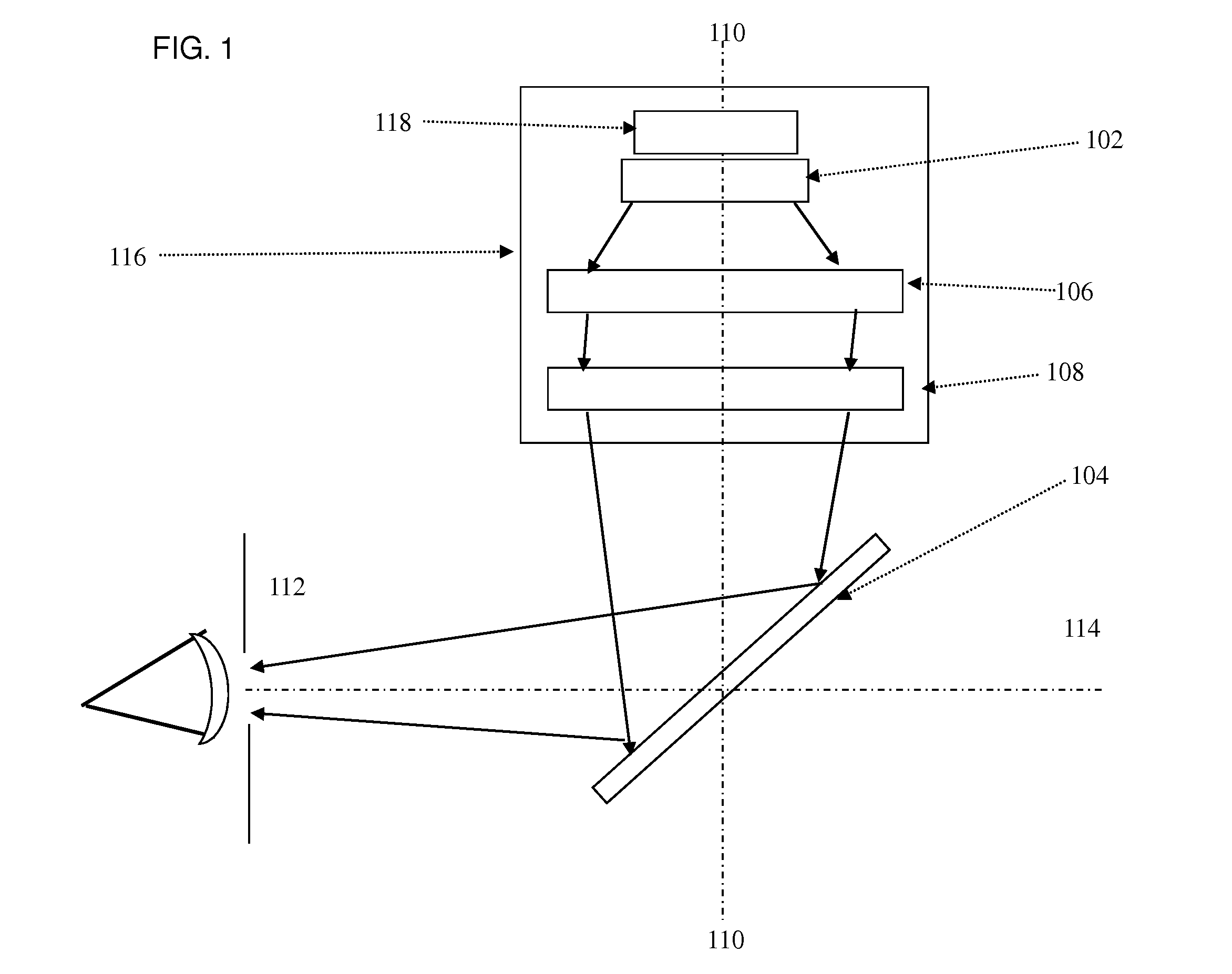
[0018]FIG. 1 shows the optical configuration of the image display device according to the present disclosure. It comprises an image source 102, first 106 and second achromatic doublet lenses 108, a beam splitter 104, and housing 116. The image source 102 and the achromatic lenses 106, 108 and the beam splitter 104 define a main optical path 110, shown in FIG. 1 by the dashed line, and are disposed in an on-axis configuration since the mechanical center of each of these elements is coincident with the main optical path.

[0019]The image source 102 generates an image t...


PUM


Abstract

Image display device having an image source generating an image, a beam splitter positioned at forty five degrees to the main optical path, to project and focus the image generated by the image source into the entrance pupil of the human eye, two achromatic standard doublet lenses positioned perpendicularly to the main optical path and placed between the image source and the beam splitter, and configured to amplify, collimate, and correct optical aberrations of said image, wherein the image source, beam splitter and the doublet lenses are in an on-axis configuration and the image display device comprises two mounting brackets parallel to the main optical axis, each having an extremity part holding an edge of the beam splitter and the other extremity pivotally attached to a housing, allowing the brackets and beam splitter to rotate in an axis perpendicular to the main optical path.

Description

FIELD[0001]The disclosed subject matter relates in general to image display devices. More particularly, this disclosure relates to a novel and improved apparatus for displaying images through a see-through head mounted display (HMD).DESCRIPTION OF THE RELATED ART[0002]Generally, see-through HMDs comprise a housing having therein an image source and a set of projection optical elements (e.g., lenses, mirrors, prisms and beam splitters), some of which are placed in front of the user's eyes. Different types of see-through HMDs are known from. Normally, see-through HMDs have an off-axis optical configuration which introduces significant optical aberrations that need to be accounted for and subsequently corrected. Additionally, the HMDs are less tolerant of misalignments in the optical elements.[0003]In order to correct these optical aberrations, additional or custom-made optical elements are normally used (e.g., doublet lenses or aspheric lenses). The need for optimal alignment between ...

Claims


Application Information

Patent Timeline
IPC IPC(8): G02B27/01
CPCG02B7/002G02B27/0172G02B2027/0138G02B2027/0116G02B2027/011B33Y80/00
Inventor MARTINS, MIGUEL MARQUES
Owner MIGUEL MARQUES MARTINS
Why Eureka
Try Eureka