Handheld Transducer Scanning Speed Guides and Position Detectors

a transducer and speed guide technology, applied in the field of non-invasive external ultrasound lipoplasty and skin tightening, can solve the problems of reducing the efficacy of the procedure to near zero, affecting the effect of the procedure, and causing indiscriminate tissue destruction,

Inactive Publication Date: 2010-10-07
NIVASONIX
View PDF12 Cites 85 Cited by
  • Summary
  • Abstract
  • Description
  • Claims
  • Application Information

AI Technical Summary

Problems solved by technology

Too short an exposure time (fast motion) will not give adequate cavitation or heat (when needed) and could therefore reduce the efficacy of the procedure to near zero.
Too slow a motion could create too much cavitation or heat with the potential for indiscriminant tissue destruction.

Method used


Image

  • Handheld Transducer Scanning Speed Guides and Position Detectors
  • Handheld Transducer Scanning Speed Guides and Position Detectors
  • Handheld Transducer Scanning Speed Guides and Position Detectors

Examples


first embodiment

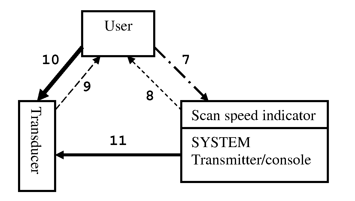
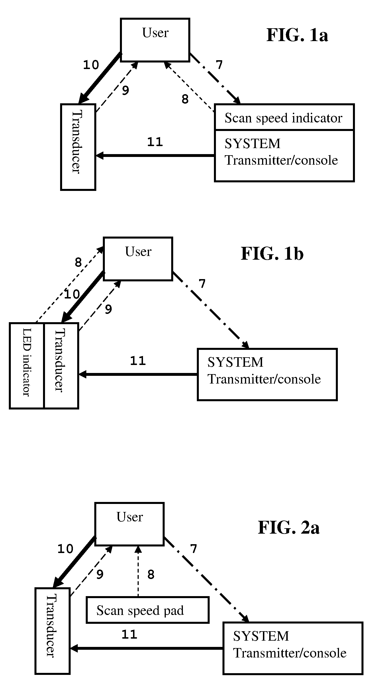
[0023]One method requires the user to be part of the feedback loop, whereby the system, the transducer, or a separate device acts as a visual guide for the user to apply the desired scanning speed. The first embodiment is an example of this approach.

second embodiment

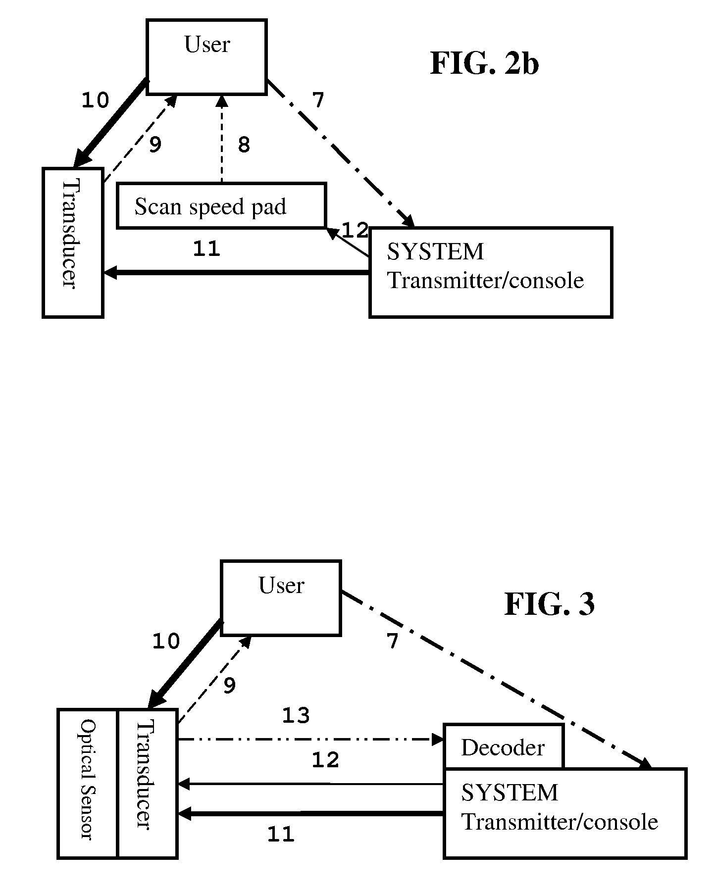
[0024]Another method consists of a subsystem that detects the transducer scanning velocity and in real time transfers this information to the system, which in turn adjusts parameters such as MI and TI (i.e., ultrasound dose) to achieve the desired effect based on the actual speed of transducer movement. This relieves the user from precisely matching the desired scanning speed, but still requires the user to keep track of the transducer position and the ultrasound beam focal depth. The second embodiment is an example of this.

third embodiment

[0025]A third method monitors the transducer position, which is transferred to the system in real time. With this information and the presence of a clock, the transducer velocity may also be easily calculated. Now the system can automatically adjust the needed parameters such as MI, TI and focal length to accomplish the planned treatment, giving the user the freedom to move the transducer almost “at will”. The third embodiment is an example of this.

[0026]It should be noted that there is much more value in using a 3D coordinate system, where the (contoured) skin defines two of the dimensions and the depth below the skin surface is the third, rather than a Cartesian coordinate system fixed to the operating room or even fixed to localized patient movements.

[0027]The connecting lines in the functional block diagrams in FIGS. 1a to 3 have the following meaning. The occasional user control of the system / console is shown as 7. Item 8 indicates that the user reads the scanning speed indicat...


PUM


Abstract

Methods for controlling and monitoring speed and position of a handheld medical transducer. Three methods are presented of various means, two of which include the user in the feedback loop and the third is fully automatic. In the third, an optical position sensor similar to an optical computer mouse provides enough information that the system can respond to and correct for a freehand scanning motion by the user.

Description

CROSS-REFERENCE TO RELATED APPLICATION[0001]This application claims the benefit of U.S. Provisional Patent Application No. 60 / 995,895 filed Sep. 28, 2007.BACKGROUND OF THE INVENTION[0002]1. Field of the Invention[0003]The present invention relates to the field of non-invasive external ultrasound lipoplasty, skin tightening, and various non-invasive aesthetic, dermatologic, and therapeutic applications.[0004]2. Prior Art[0005]During a non-invasive external ultrasound lipoplasty, skin tightening, aesthetic, dermatologic, or other therapeutic procedure with a handheld transducer, it becomes particularly important to apply and distribute the ultrasound energy dose according to the amount and location of the fat to be emulsified, the degree and location of skin tightening needed, or the extent and type of aesthetic, dermatologic, or other therapeutic desired effect.[0006]For this purpose the transducer's movement or instantaneous scanning speed needs to be known or better yet its positio...

Claims


Application Information

Patent Timeline
Patent Type & Authority Applications(United States)
IPC IPC(8): A61N7/00A61B8/00
CPCA61B2017/00115A61N2007/0008A61N7/02
Inventor PEDERSEN, LAUST G.DAVLANTES, CONSTANTINE C.
Owner NIVASONIX
Why Eureka
Try Eureka