Mixing device

a technology of mixing device and mixing chamber, which is applied in the direction of packaging foodstuffs, packaged goods types, pharmaceutical containers, etc., can solve the problems of inefficiency of holding chamber, harmful effects of unreliable devices, and inability to produce conventional mixing devices, etc., and achieves reliable and easy-to-make effects

Inactive Publication Date: 2010-10-07
HO PHILLIP PHUNG I
View PDF3 Cites 19 Cited by
  • Summary
  • Abstract
  • Description
  • Claims
  • Application Information

AI Technical Summary

Benefits of technology

[0008]The main objective of the invention is to p

Problems solved by technology

Such malfunctioning caused by an unreliable device may be harmful if not fatal in a dental or surgical event.
Furthermore, a manufacturer will find production of the conventional mixing device, which requires packing agents into cartridges and inserting the same into the holding chambers to be ine

Method used


Image

  • Mixing device
  • Mixing device
  • Mixing device

Examples


first embodiment

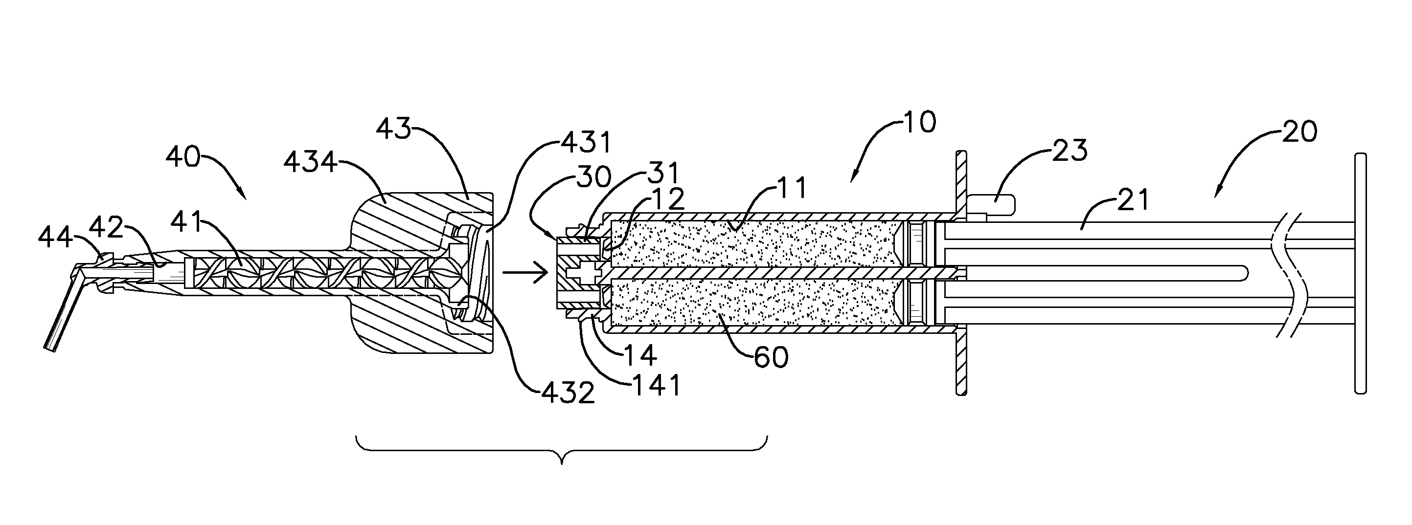
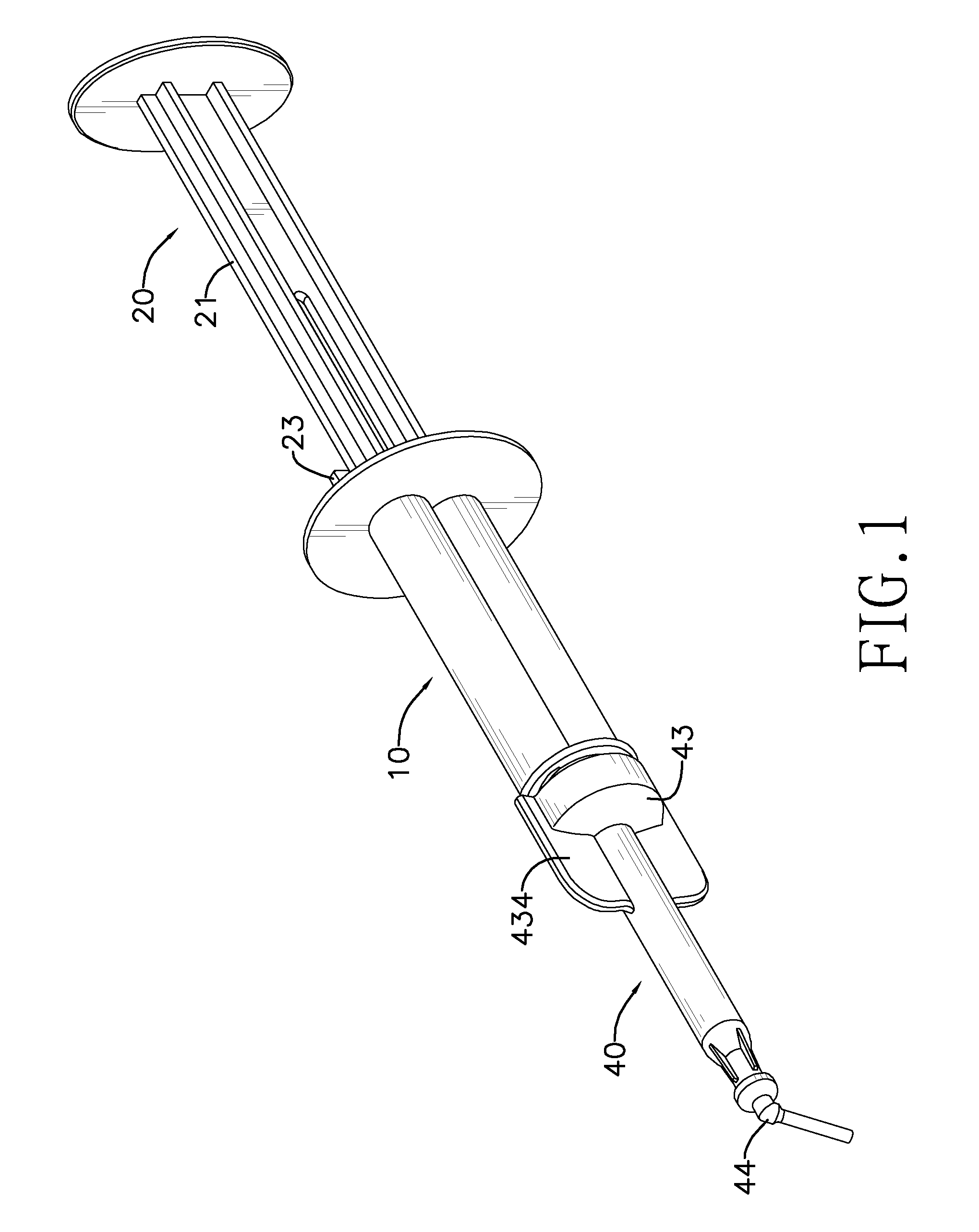
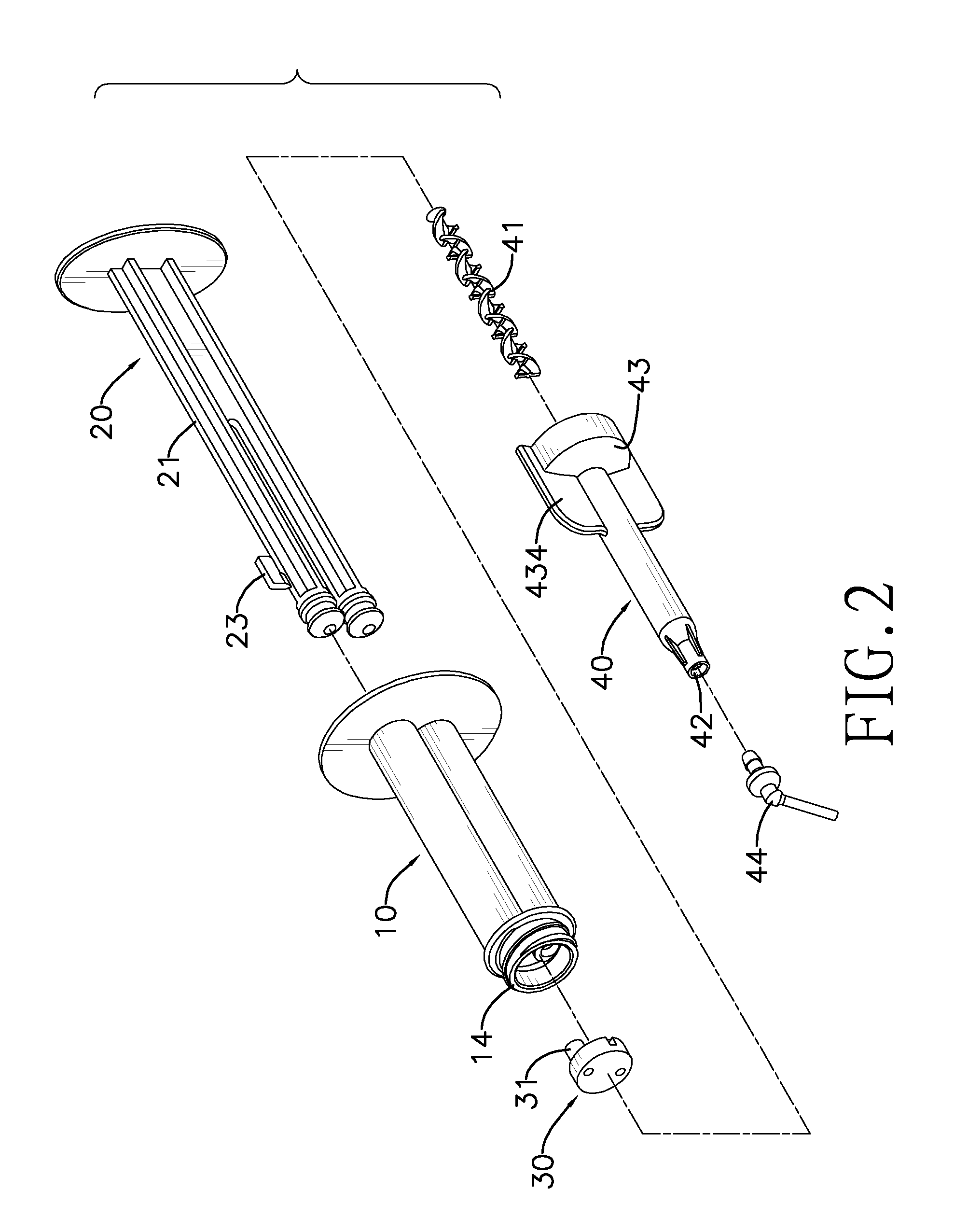
[0031]With reference to FIGS. 1-3, the mixing device in accordance with the present invention comprises a body (10), a pusher (20), an abutter (30) and a mixer (40).

[0032]The body (10) is tubular and comprises a fore end, a rear end, an outer surface and multiple chambers (11). Each chamber (11) comprises a fore opening, a rear opening and a cap (12). The fore opening and the rear opening of the chamber (11) respectively correspond to the fore end and rear end of the body (10). With reference to FIG. 5, the cap (12) is mounted to and seals the fore opening of the chamber (11), protrudes forwardly and comprises an outer surface and a top. The cap (12) is used to seal an agent (60) within the chamber (11) preventing leakage of the agent (60) from the fore opening of the chamber (11). The cap (12) is preferably injection-molded to the fore opening of the chamber (11).

[0033]With reference to FIGS. 2 and 3, the pusher (20) has multiple rods (21). The rods (21) are to be respectively inse...

second embodiment

[0045]With reference to FIGS. 7-9, the mixing device in accordance with the present invention also has a body (10A), a pusher (20A), an abutter (30A) and a mixer (40A).

[0046]The body (10A) is tubular and has a fore end, a rear end and multiple chambers (11A). Each chamber (11A) has a fore opening, a rear opening and a cap (12A). The fore opening and the rear opening respectively correspond to the fore end and rear end of the body (10A). With reference to FIG. 11, the cap (12A) is injection-molded and mounted to and seals the fore opening of the chamber (11A). The cap (12A) protrudes forwardly and comprises an outer surface (121A) and a top (122A).

[0047]With further reference to FIGS. 8 and 9, the pusher (20A) of the second embodiment of the mixing device has multiple rods (21A). The rods (21A) are respectively inserted in the chambers (11A) from the rear opening thereof for pushing the agents (60) filled in the chambers (11A) forwards.

[0048]With reference to FIG. 10, the abutter (30...

third embodiment

[0057]With reference to FIG. 12, the top (122B) of each of the caps (12B) of the mixing device has an outer portion near the outer surface of the body (10A) and an inner portion away from the outer surface of the body (10A). The outer portion forwardly protrudes more than the inner portion. When pushed by the tube (31B) of the abutter (30B), the outer portion contacts the blunt end of the tube (31B) first and takes more pressure therefrom, which also leads to easy breakage of the cap (12B).


PUM


Abstract

A mixing device having a body, a pusher, an abutter and a mixer is provided. The body is tubular and has a fore end, a rear end and multiple chambers. Each chamber has a fore opening, a rear opening and a cap sealing the fore opening. The cap protrudes forwardly and has an outer surface and a top. The pusher has multiple rods respectively inserted in the chambers from the rear openings. The abutter has multiple tubes for respectively breaking the caps through to communicate with the chambers and each having a blunt end. The mixer is tubular and has an outlet, a connector and a mixing shaft mounted therein. The connector is connected to the fore end of the body and communicates with the tubes of the abutter. The cap may be easily injection-molded and agents may be filled directly into the chambers to ensure reliable operation.

Description

BACKGROUND OF THE INVENTION[0001]1. Field of the Invention[0002]The present invention relates to a mixing device, especially to a device for mixing more than two agents into a pharmaceutical composition.[0003]2. Description of the Prior Art[0004]Various dental or surgical pharmaceutical compositions need to be made right before use to prevent unexpected degradation that may cause solidification or sharp drop of medical activity. Conventional mixing devices are developed to quickly mix the agents and conveniently use the composition. As disclosed in U.S. Pat. No. 6,352,177, one of such conventional mixing devices has two holding chambers into which two cartridges are respectively inserted. To make and use a composition from the agents packed in the two cartridges, the user pierces the cartridges respectively with two piercing tubes. The agents are forwarded into a mixing chamber, where they are mixed into a pharmaceutical composition, through the tubes. The user may then output and u...

Claims


Application Information

Patent Timeline
IPC IPC(8): A61J1/14
CPCA61C5/064A61C5/062A61C5/62A61C5/64
Inventor HO, PHILLIP PHUNG-ILEE, CHUNG-CHIEH
Owner HO PHILLIP PHUNG I
Why Eureka
Try Eureka