

Digital thermal binder and powder printing
A thermal printing head, digital printing technology, applied in printing, ink transfer from original manuscript, copying/marking method, etc., can solve the problems of hours-consuming, low productivity of 3D printing machine, not too transparent, etc., and achieve cost saving Effect
- Summary
- Abstract
- Description
- Claims
- Application Information
AI Technical Summary
Problems solved by technology
Method used
Image

Examples
example 1
[0288] Example 1 - Dry Fiber Based Ink
[0289] The dry ink powder was prepared by mixing 20% by weight spray-dried melamine formaldehyde resin particles, 20% dark brown pigment and 60% pine wood fibers (average length about 0.2mm and thickness about 0.05mm) have to. The mixture was applied as a 1 mm thick layer on the steel belt by means of a spreading device. Thereafter the powder mixture is heated and moisture is applied by steam from deionized water. The mixture is dried by hot air, resulting in a hard and stable powder-based surface layer with a semi-cured melamine binder. The dry layer was removed from the belt by scraping and the dry wood particles coated with pigment and melamine resin were ground and sieved into dry ink colorants of a size similar to that of individual wood fibers. A dry ink comprising a colorant is obtained with a wood fiber body and a surface covered by pigment bound to the fibers by a semi-cured melamine resin.
example 2
[0290] Example 2 - Digital Printing Using Thermal Printheads
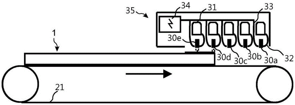
[0291] A high density fiber (HDF) core of 8 mm was sprayed with small droplets of deionized water and contained 300 g / m of wood fibers, melamine particles, brown pigments and alumina particles 2The powder mixture is applied to the HDF core board by spreading equipment. The mixture was again sprayed with deionized water containing a release agent and dried by infrared lamps to obtain a hard stable, partially semi-cured powder-based surface bonded to the HDF core and having a beige base color. Panels with a stable powder surface are placed on a conveyor belt and moved under a digital Kyocera piezoelectric print head. Dry ink as described above in Example 1, comprising a darker brown than the basic beige powder-based surface, in a second step utilizing a dry ink application station comprising a hopper and a 5 cm diameter rotating and oscillating engraved roller To be sprinkled over the entire powder-based surface. ...
Embodiment
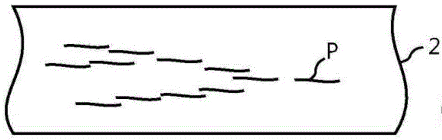
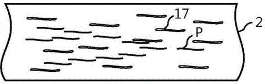
[0293] 1. A method of forming a digital print (P) on a surface (2), wherein said method comprises the steps of:
[0294] - applying a colorant (7) to said surface (2);
[0295] - bonding a portion of said colorant to said surface (2) with a binder (11); and
[0296] • Removal of unbound colorant (7) from said surface (2) such that a digital print (P) is formed by said bound colorant (7).
[0297] 2. The method as in embodiment 1, wherein the colorant (7) comprises a pigment (12) mixed with the binder (11).
[0298] 3. The method as in embodiment 1 or 2, wherein the binder (11) comprises a thermosetting resin.
[0299] 4. The method according to any one of the preceding embodiments, wherein the binder (11) comprises a thermoplastic resin.
[0300] 5. The method according to any one of the preceding embodiments, wherein the binder (11) is a powder.
[0301] 6. The method as claimed in any one of the preceding embodiments, wherein the surface (2) is a paper layer or a foil. ...
PUM
| Property | Measurement | Unit |
|---|---|---|
| thickness | aaaaa | aaaaa |
| particle size | aaaaa | aaaaa |
| diameter | aaaaa | aaaaa |
Abstract
Description
Claims
Application Information