Slickline Conveyed Debris Management System

Active Publication Date: 2010-10-14
BAKER HUGHES INC
View PDF75 Cites 68 Cited by
  • Summary
  • Abstract
  • Description
  • Claims
  • Application Information

AI Technical Summary

Benefits of technology

[0010]A wellbore cleanup tool is run on slickline. It has an onboard power supply and circulation pump. Inlet flow is at the lower end into an inlet pipe that keeps up fluid velocity. The inlet pipe opens to a surrounding annular volume for sand containment and the fluid continues through a screen and into the pump for eventual exhaust back into the water in the wellbore. A modular structure is envisioned to add debris

Problems solved by technology

There are limits to which techniques can be used with low pressure formations.
Techniques that involve pressurized fluid circulation present risk of fluid loss into a low pressure formation from simply the fluid column hydrostatic pressure that is created when the well is filled with fluid and circulated or jetted.
The productivity of the formation can be adversely affected should such flow into the formation occur.
The downside of this technique is the cost of the specialized foam equipment and the logistics of getting such equipment to the well site in remote locations.
These systems can have operational issues with sand buildup on the seats for the flappers that keep them from sealing and as a result some of the captured sand simply escapes again.
The reciprocation debris collection systems also have the issue of a la

Method used


Image

  • Slickline Conveyed Debris Management System
  • Slickline Conveyed Debris Management System
  • Slickline Conveyed Debris Management System

Examples


Embodiment Construction

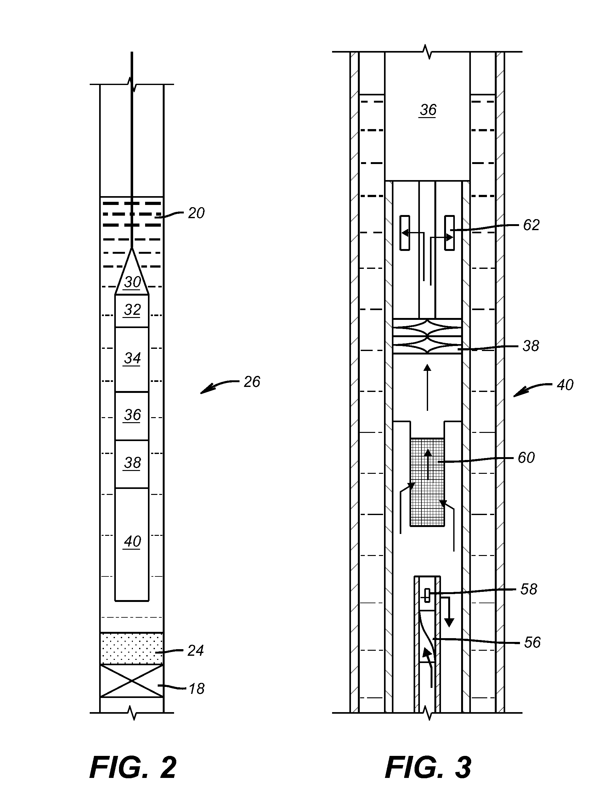
[0024]FIG. 2 shows the tool 26 lowered into the water 20 on a slickline or non-conductive cable 28. The main features of the tool are a disconnect 30 at the lower end of the cable 28 and a control system 32 for turning the tool 26 on and off and for other purposes. A power supply, such as a battery 34, powers a motor 36, which in turn runs a pump 38. The modular debris removal tool 40 is at the bottom of the assembly.

[0025]While a cable or slickline 28 is preferred because it is a low cost way to rapidly get the tool 26 into the water 20, a wireline can also be used and surface power through the wireline can replace the onboard battery 34. The control system can be configured in different ways. In one version it can be a time delay energized at the surface so that the tool 26 will have enough time to be lowered into the water 20 before motor 36 starts running. Another way to actuate the motor 36 is to use a switch that is responsive to being immersed in water to complete the power d...


PUM


Abstract

A wellbore cleanup tool is run on slickline. It has an onboard power supply and circulation pump. Inlet flow is at the lower end into an inlet pipe that keeps up fluid velocity. The inlet pipe opens to a surrounding annular volume for sand containment and the fluid continues through a screen and into the pump for eventual exhaust back into the water in the wellbore. A modular structure is envisioned to add debris carrying capacity. Various ways to energize the device are possible. Other tools run on slickline are described such as a cutter, a scraper and a shifting tool. A motor driven by an onboard power supply operates the circulation pump as well as a vibration device to agitate the debris and prevent coring into the debris if compacted. A shroud presents an alternate flow path if the housing lower end is embedded in debris.

Description

[0001]This application is a continuation-in-part of application Ser. No. 12 / 423,044 filed Apr. 14, 2009.FIELD OF THE INVENTION[0002]The field of this invention is tools run downhole preferably on cable and which operate with on board power to perform a downhole function and more particularly wellbore debris cleanup.BACKGROUND OF THE INVENTION[0003]It is a common practice to plug wells and to have encroachment of water into the wellbore above the plug. FIG. 1 illustrates this phenomenon. It shows a wellbore 10 through formations 12, 14 and 16 with a plug 18 in zone 16. Water 20 has infiltrated as indicated by arrows 22 and brought sand 24 with it. There is not enough formation pressure to get the water 20 to the surface. As a result, the sand 24 simply settles on the plug 18.[0004]There are many techniques developed to remove debris from wellbores and a good survey article that reviews many of these procedures is SPE 113267 Published June 2008 by Li, Misselbrook and Seal entitled San...

Claims


Application Information

Patent Timeline
IPC IPC(8): E21B43/34
CPCE21B2023/008E21B37/00E21B23/001
Inventor LYNDE, GERALD D.
Owner BAKER HUGHES INC
Why Eureka
Try Eureka