Surface crack sealing method

a surface crack and sealing technology, applied in the direction of manufacturing tools, soldering devices, nuclear elements, etc., can solve the problems of pits in the sealing/welding step, the difficulty of individually or independently controlling the diameter of the preceding and subsequent laser beams,

Active Publication Date: 2010-10-14
KK TOSHIBA
View PDF3 Cites 7 Cited by
  • Summary
  • Abstract
  • Description
  • Claims
  • Application Information

AI Technical Summary

Benefits of technology

[0018]According to the present invention having the features described above, a surface crack can be sealed in a satisfactory manner with no pits or other detects left behind even when water, oxides and other substances are present in the surface crack.

Problems solved by technology

However, if water, oxides, and other substances are present inside the surface crack, in the sealing methods mentioned above, a mixture thereof is vaporized when heated by the laser beam.
In the conventional technique described above, since two laser beams are focused through a common optical system, it is difficult to individually or independently control the diameters of the preceding and subsequent laser beams, and hence, the preceding laser beam heats and melts the surface.
If the surface is melted and the surface defect is sealed, the water and oxides left in the crack are vaporized by the heat in the subsequent sealing / welding step and the vapor pressure increases, which may produce pits in the sealing / welding step in some cases.

Method used


Image

  • Surface crack sealing method
  • Surface crack sealing method
  • Surface crack sealing method

Examples


first embodiment

FIGS. 1 to 3

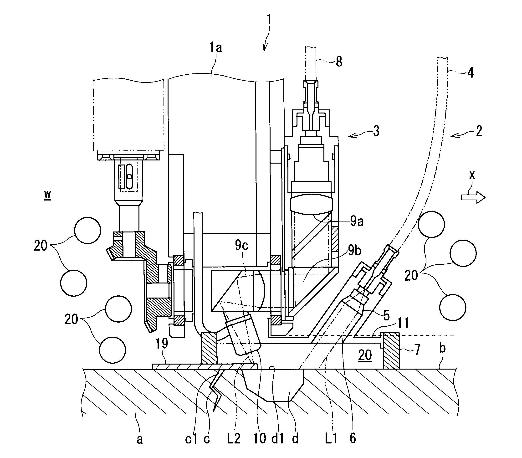
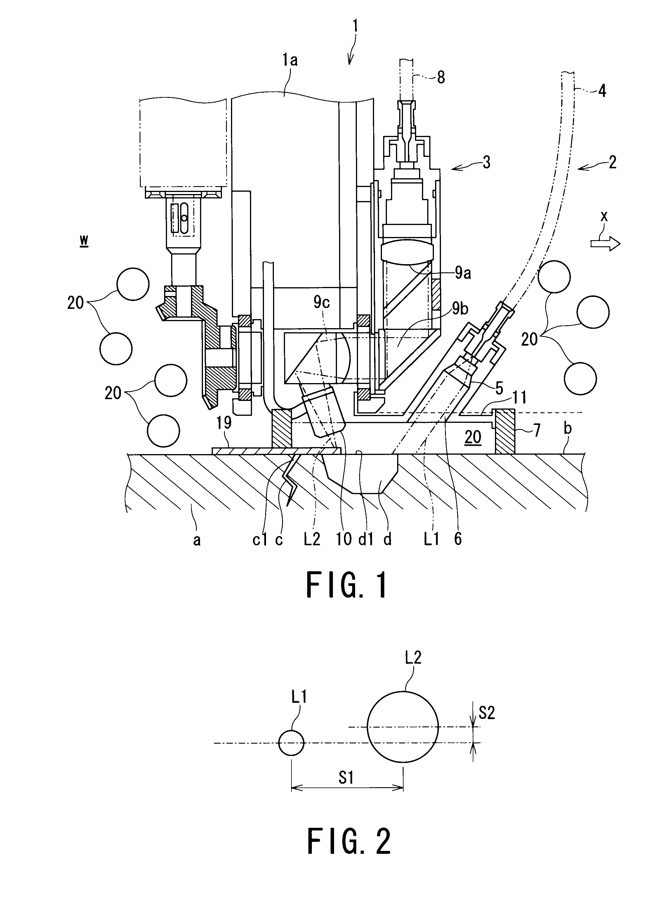
[0024]FIG. 1 is a view for explaining a surface crack sealing method according to a first embodiment of the present invention and shows the configuration of an essential portion of a welding apparatus. FIGS. 2 and 3 are views for explaining functions of the welding apparatus.

[0025]As shown in FIG. 1, when a reactor is inspected, for example, a welding apparatus 1 is suspended in a reactor water “w” for the purpose of sealing cracks “c” and “d” having openings c1 and d1 and produced in a surface “b” of a member “a”, which is a structural member constituting the reactor.

[0026]FIG. 1 shows a welding head 1a disposed at a lower end of the welding apparatus 1. The welding head 1a includes two sets of laser devices, first and second laser devices 2 and 3.

[0027]The first laser device 2 is a heating laser device and irradiates the regions of the member “a” where the cracks are produced with a heating laser beam L1 to heat the regions to a temperature lower than the melting point...

second embodiment

FIG. 4

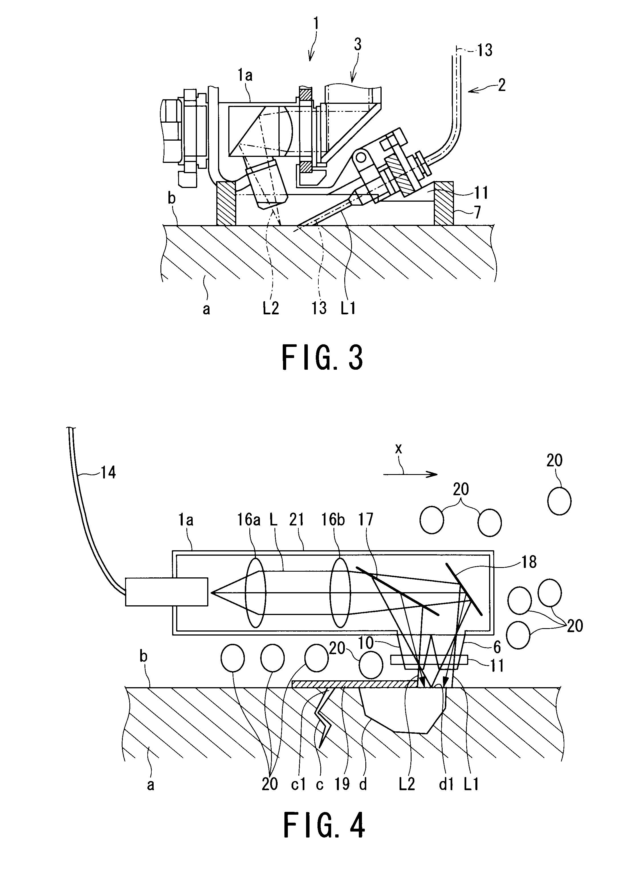
[0049]In this second embodiment, a surface crack sealing method, in which a laser beam L transmitted through a single optical fiber 14 is divided by a half-silvered mirror 17 into the heating laser beam L1 and the welding laser beam L2, will be described.

[0050]In the present embodiment, only the way of applying the heating laser beam L1 and the welding laser beam L2 differs from that in the first embodiment, and accordingly, the same reference numerals are added to portions and / or members in FIG. 4 corresponding to those in FIG. 1 representing the first embodiment, and duplicated explanations are omitted herein.

[0051]As shown in FIG. 4, in the present embodiment, the half-mirror 17 and a total reflection mirror 18 are provided in a casing 21 that houses the welding head 1a, unlike the first embodiment. The half-mirror 17 and the total reflection mirror 18 are used to divide the laser beam L transmitted through the single optical fiber 14 into the heating laser beam L1 and the ...


PUM

PropertyMeasurementUnit
distanceaaaaaaaaaa
temperatureaaaaaaaaaa
melting pointaaaaaaaaaa

Abstract

A method of sealing a surface crack in a member is provided includes steps of irradiating a region of the member at which the crack is produced with a heating laser beam so as to heat the region to a temperature lower than a melting point of the member, and then irradiating a region of the member at which the crack is produced with a welding laser beam subsequent to irradiation of the heating laser beam so as to heat the region to a temperature higher than or equal to the melting point of the member, thereby sealing an opening of the surface crack of the member.

Description

TECHNICAL FIELD[0001]The present invention relates to a surface crack sealing method for sealing a crack produced in a surface of a member constituting a nuclear reactor or any other similar structure by irradiating the surface of the member with a laser beam to melt the surface.BACKGROUND ART[0002]In a conventional technology, when cracks are produced in surfaces of members constituting a nuclear reactor or any other similar structures, for example, the constitutional member is entirely exchanged or a reinforcing member is placed. In order to repair a cracked portion itself, various methods have been proposed, such as a method in which a cracked portion is removed by mechanical machining or electrical discharge machining and then filling the cracked portion with a suitable material by using TIG arc welding or laser welding and a method in which only a surface crack is welded and sealed.[0003]In conventional surface crack sealing methods, the surface of a structural member on which ...

Claims


Application Information

Patent Timeline
Patent Type & Authority Applications(United States)
IPC IPC(8): B23K26/00B23K26/064B23K26/067B23K26/21B23K26/34G21C19/02
CPCB23K26/067B23K26/34B23P6/04G21C19/02B23K35/0272B23K26/0608B23K35/0255B23K35/0261B23K26/0604
Inventor TAMURA, MASATAKAMAKINO, YOSHINOBUKONO, WATARUSHIIHARA, KATSUNORITANAKA, YOSHIMIYODA, MASAKIHAMAMOTO, YOSHIOOKADA, SATOSHIKATO, HIROMI
Owner KK TOSHIBA
Why Eureka
Try Eureka