Utility holder

a utility line and holder technology, applied in the field of utility holder, can solve the problems of increasing the installation space of multiple holders, increasing the complexity of prior art holding devices, and increasing the cost of installing multiple individual holders, and achieves the effect of strong retention properties

Inactive Publication Date: 2010-10-14
HALEXSCOTT FETZER
View PDF30 Cites 37 Cited by
  • Summary
  • Abstract
  • Description
  • Claims
  • Application Information

AI Technical Summary

Benefits of technology

[0014]Yet another advantage of the present invention is that it provides stronger retention properties than known open-profile utility holders.
[0015]Still other benefits and advantages of the invention will become apparent to those skilled in the art to which it pertains upon a reading and understanding of the following detailed specification.

Problems solved by technology

Even the more complicated prior art holding devices come only in predetermined configurations to hold a single utility line.
It is inefficient and more costly to install multiple individual holders to retain several utility lines.
Additionally it requires more installation space to use multiple holders and space is often limited.

Method used


Image

  • Utility holder
  • Utility holder
  • Utility holder

Examples


Embodiment Construction

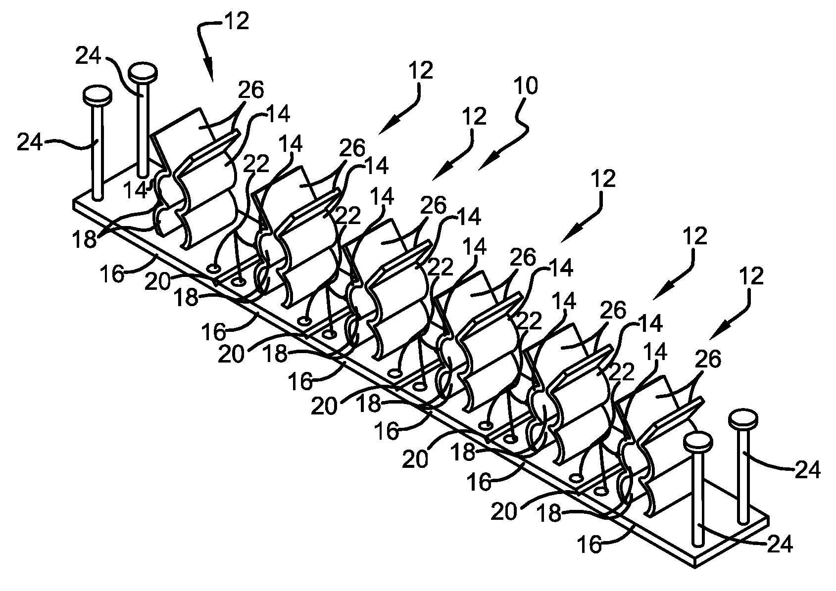
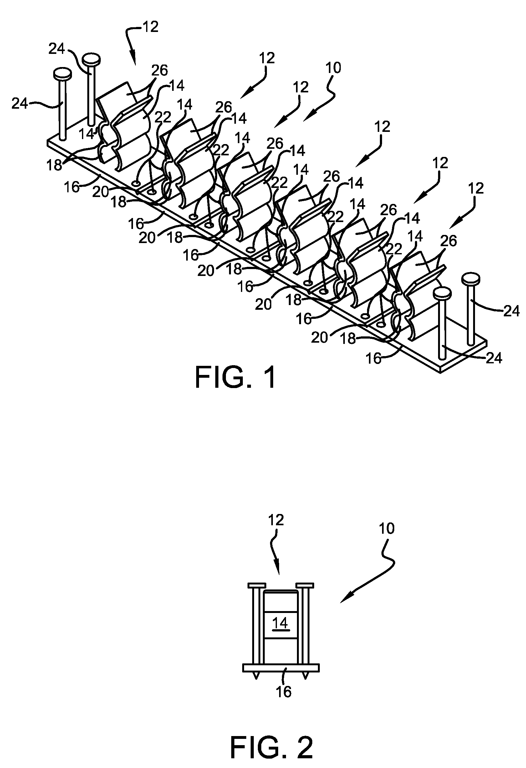
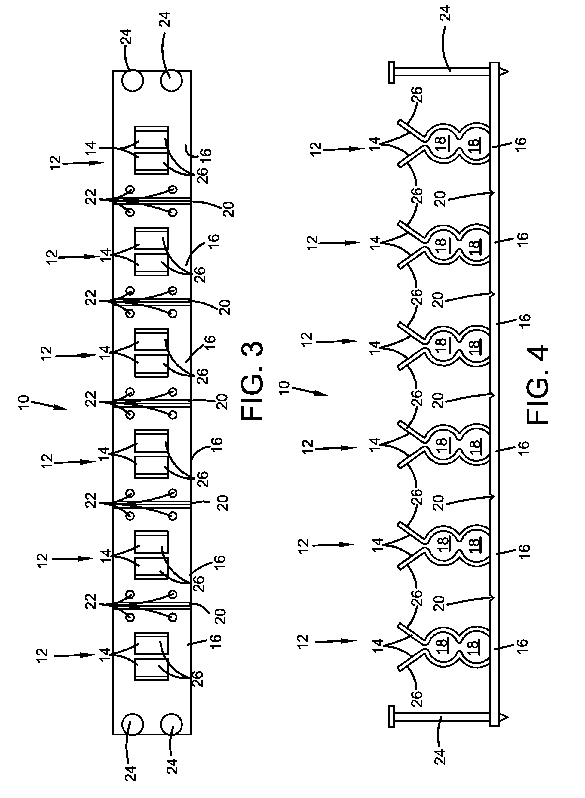
[0026]Referring now to the drawings wherein the showings are for purposes of illustrating embodiments of the invention only and not for purposes of limiting the same, and wherein like reference numerals are understood to refer to like components, FIGS. 1-4 shows a row 10 of utility holders 12 in accordance with a first embodiment. The row 10 includes six holders 12, but may include any desired number. Each utility holder 12 includes at least two pairs of fingers 14 extending from a base 16. Each pair of fingers 14 defines at least one receiving section 18. Each receiving section 18 is suitable to hold a utility line such as, but not limited to, a high or low voltage electrical cable, electrical conduit, plumbing supply or drain lines, HVAC lines, and the like. For example, some non limiting examples of acceptable cable include: traditional AC / MC cable (of various sizes, including but not limited to, 14-2, 12-2, and 14-3); non-metallic sheathed cable (“NM” cable of various sizes, inc...


PUM

PropertyMeasurementUnit
forceaaaaaaaaaa
elasticaaaaaaaaaa
shapeaaaaaaaaaa

Abstract

A utility holder which may be used to retain utility lines may include a holder having a first portion having at least two pairs of fingers defining at least two receiving sections wherein the receiving sections may be sized to accept utility lines; a second portion having a base wherein the pairs of fingers extend from the base with the longitudinal axes of the receiving sections being substantially parallel.

Description

[0001]This application claims priority to U.S. Ser. No. 61 / 169,136, entitled UTILITY HOLDER, filed Apr. 14, 2009, which is incorporated herein by reference.BACKGROUND [0002]A. Field of Invention[0003]This invention generally relates to methods and apparatuses concerning installation of utility lines and more specifically relates to methods and apparatuses concerning holders for utility lines.[0004]B. Description of the Related Art[0005]It is well known to utilize clamping or holding devices to secure utility lines to structural surfaces of buildings or support members of a frame. The prior art holding devices include U-shaped clamps made from elastic sheet metal that are secured over positioned utility lines or cables, and in some instances “open-profile” devices that are secured to the support surface before accepting utility lines, but the most commonly used holding devices are common heavy duty staples. Even the more complicated prior art holding devices come only in predetermine...

Claims


Application Information

Patent Timeline
Patent Type & Authority Applications(United States)
IPC IPC(8): F16L3/22B23P19/04
CPCF16L3/13F16L3/223Y10T29/53F16L3/237H02G3/32F16L3/23
Inventor GARDNER, MICHAEL J.BAKER, GLENN A.
Owner HALEXSCOTT FETZER
Why Eureka
Try Eureka