Selectable coil array

a coil array and coil technology, applied in the direction of mobile unit charging stations, transportation and packaging, and battery arrangement for several simultaneous batteries, can solve the problems of limiting the operation of the charger with one secondary device, restricting the spatial freedom, and limiting the spatial freedom of the inductive power supply, so as to facilitate efficient power transfer and increase the general effect of wireless power transfer efficiency

Active Publication Date: 2010-10-14
PHILIPS IP VENTURES BV
View PDF59 Cites 324 Cited by
  • Summary
  • Abstract
  • Description
  • Claims
  • Application Information

AI Technical Summary

Benefits of technology

[0010]In one embodiment, a coil array system is provided that includes overlapping coils where different coils can be turned on or off. This makes it possible to provide power at any point on the surface, thus giving spatial freedom across the surface, while giving the primary control over which areas are provided power. This can decrease losses due to parasitic loads, as well as increase efficiency by providing better coupling between the primary and secondary coils.
[0012]In another embodiment, each coil in the coil array is connected to a separate series resonant capacitor. Each capacitor, in conjunction with the coil it is connected to, forms a tank circuit with a particular resonant frequency. When multiple tank circuits are connected in parallel, the resonant frequency of the system is generally maintained as each additional tank circuit is added to the system. This facilitates efficient power transfer to the secondary coil independent of the number of coils selected to be energized because wireless power transfer efficiency is generally increased where the primary coil resonant frequency and the secondary coil resonant frequency are similar.

Problems solved by technology

Many inductive power supplies limit spatial freedom by requiring specific placement and orientation of the remote device with respect to the inductive power supply.
However, this requirement of close one-to-one alignment in order to effectively communicate and transmit power restricts spatial freedom and limits the charger to operation with one secondary device at a time.
The moving coil solution can increase spatial freedom but can introduce the risk of potential mechanical reliability problems.
This solution can be problematic because a larger coil may create undesired stray magnetic fields and it can be difficult to transfer power efficiently.
In addition, parasitic loads, such as pieces of metal or non-wirelessly powered devices, can absorb the magnetic field and lower the system efficiency.
One problem with a single layer array of coils is that where there are gaps between the coils, the magnetic field is lower, which is sometimes referred to as a valley.
Energizing all those coils simultaneously can lead to hot zones and dead zones due to field construction and field deconstruction effects that occur from overlapping fields.
In addition, parasitic loads, such as pieces of metal or non-wirelessly powered devices, can absorb the magnetic field and lower the system efficiency.
However, magnetic attractors add cost, complexity, and can lower efficiency of the power transfer system.
Various ergonomic alignment solutions have also been proposed, but these aids can disrupt the aesthetics of surfaces, add complexity to the design of the surface, and can affect the usability because alignment still may not be guaranteed.

Method used


Image

  • Selectable coil array
  • Selectable coil array
  • Selectable coil array

Examples


Embodiment Construction

[0044]A multi-layer coil array system in accordance with an embodiment of the present invention is shown in FIG. 8A. Other multi-layer coil array systems in accordance with additional embodiments of the present invention are shown in FIG. 11 (line multi-layer coil array) and FIG. 15 (rectangular multi-layer coil array). The multi-layer coil array system provides a charging surface where one or more remote devices can be placed in order to receive wireless power. In each of the current embodiments, the multi-layer coil array system includes an inductive power supply, a multi-layer coil array, and a controller programmed to selectively energize one or more coils within the multi-layer coil array in order to transfer power wirelessly to a device placed on the charging surface.

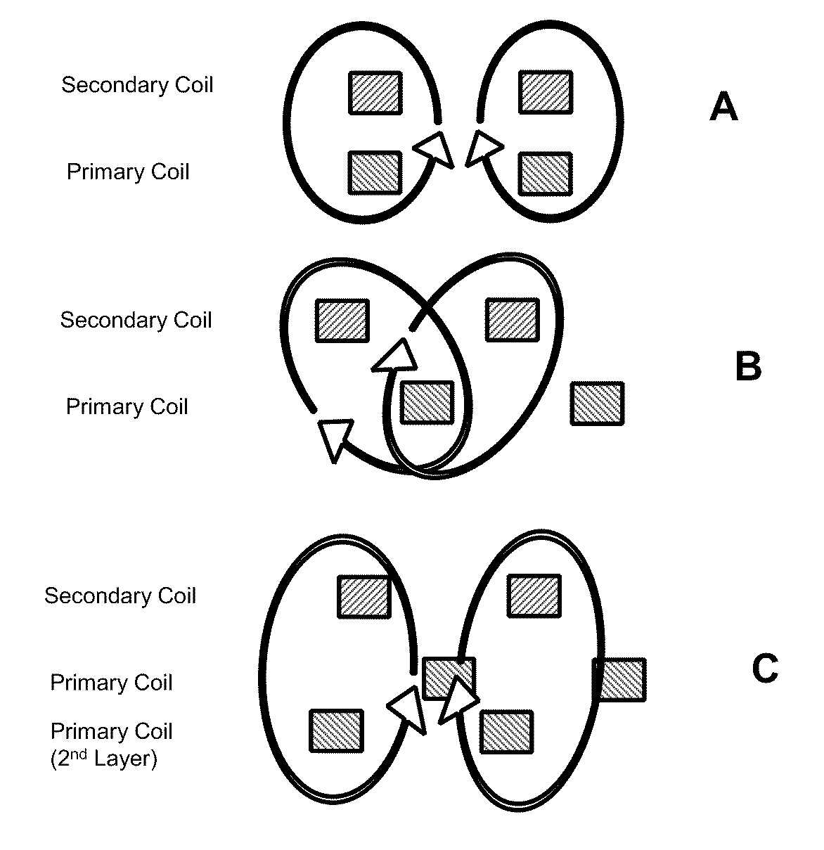
[0045]FIG. 3A-C illustrates a cross sectional representation of an inductive power system and shows the effects of field cancellation with secondary misalignment. FIG. 3A illustrates how magnetic flux flows around...


PUM


Abstract

An inductive wireless power system using an array of coils with the ability to dynamically select which coils are energized. The coil array can determine the position of and provide power to one or more portable electronic devices positioned on the charging surface. The coils in the array may be connected with series resonant capacitors so that regardless of the number of coils selected, the resonance point is generally maintained. The coil array can provide spatial freedom, decrease power delivered to parasitic loads, and increase power transfer efficiency to the portable electronic devices.

Description

FIELD OF THE INVENTION [0001]The present disclosure relates to wireless power and wireless charging.BACKGROUND OF THE INVENTION [0002]An inductive power supply may be used to supply wireless power to power or charge secondary devices. In some known inductive power supplies, secondary devices are powered or charged by placing them on a charging surface. Many inductive power supplies limit spatial freedom by requiring specific placement and orientation of the remote device with respect to the inductive power supply.[0003]In some known inductive power supply systems, a single primary coil 102 is embedded in a charging surface 104 of a charging device 106 and a single secondary coil 108 is embedded in a secondary device 110. For example, in the prior art inductive power supply system shown in FIGS. 1 and 2 one secondary coil 108 is embedded in the secondary device 110 and is aligned in close proximity to the primary coil 102 embedded in the charging device 106. Power is provided from a ...

Claims


Application Information

Patent Timeline
Patent Type & Authority Applications(United States)
IPC IPC(8): H02J7/00
CPCH02J5/005H02J7/025H02J7/0027H02J50/402H02J7/0013H02J7/0044H02J50/70H02J50/80H02J50/90H02J50/12H02J50/40H02J7/0036H03H2003/0414H02J7/00714H02J7/0042H02J2310/48
Inventor BAARMAN, DAVID W.MOORE, COLIN J.TAYLOR, JOSHUA B.MOLLEMA, SCOTT A.STONER, JR., WILLIAM T.MOES, BENJAMIN C.
Owner PHILIPS IP VENTURES BV
Why Eureka
Try Eureka