Bridgeless PFC converter

a converter and bridge technology, applied in the direction of power conversion systems, electric variable regulation, instruments, etc., can solve the problems of 3% additional losses, 6% total conversion losses, and the converter is not capable of accepting alternating input voltages

Inactive Publication Date: 2010-10-14
CUKS
View PDF7 Cites 66 Cited by
  • Summary
  • Abstract
  • Description
  • Claims
  • Application Information

AI Technical Summary

Problems solved by technology

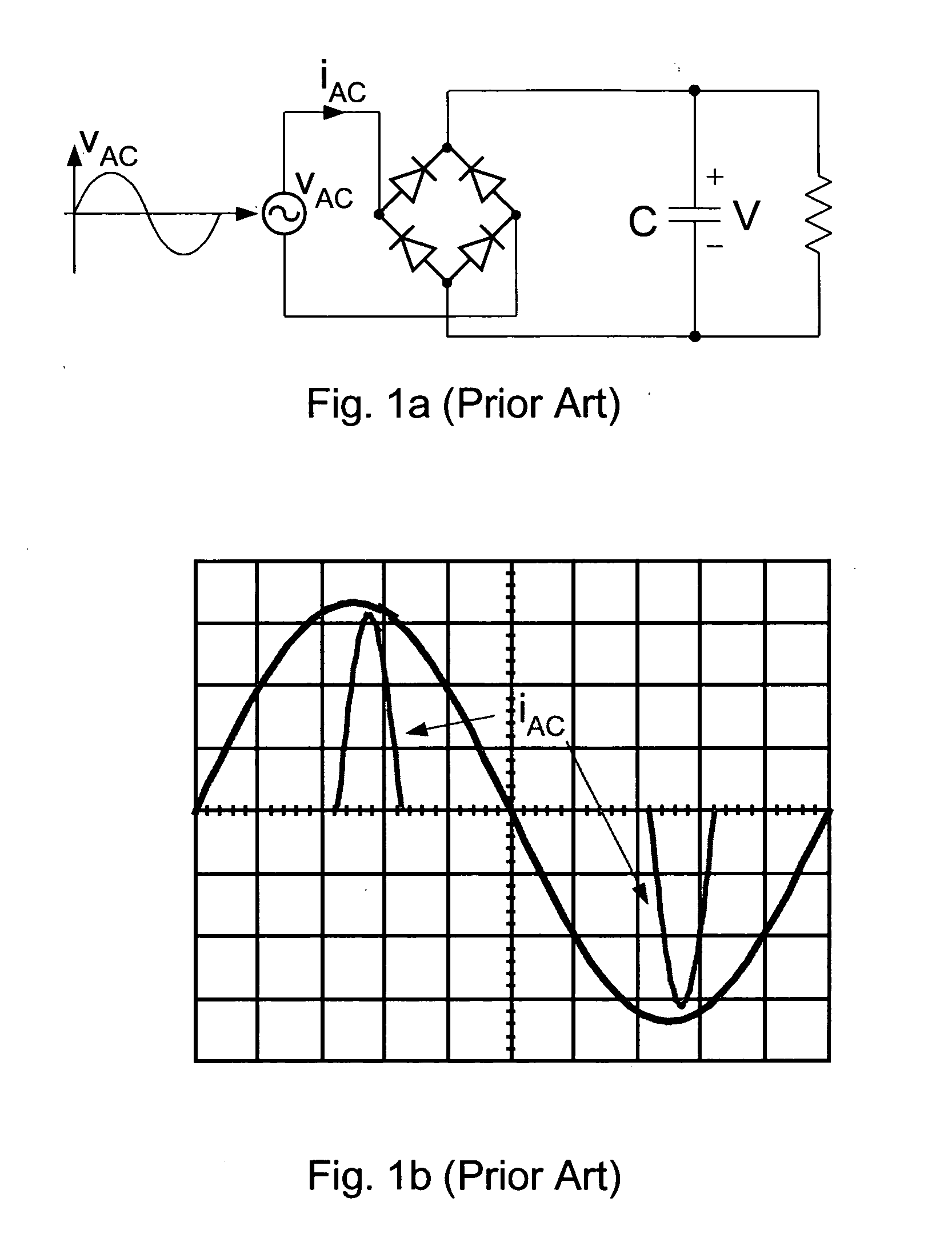
Therefore, this converter is not capable to accept an alternating input voltage, which might change its polarity, from positive to negative and vice verse with respect to ground and still generate a positive output DC voltage V. In fact, all presently known DC-DC single-stage power converters have the same limitations of one voltage polarity on input.
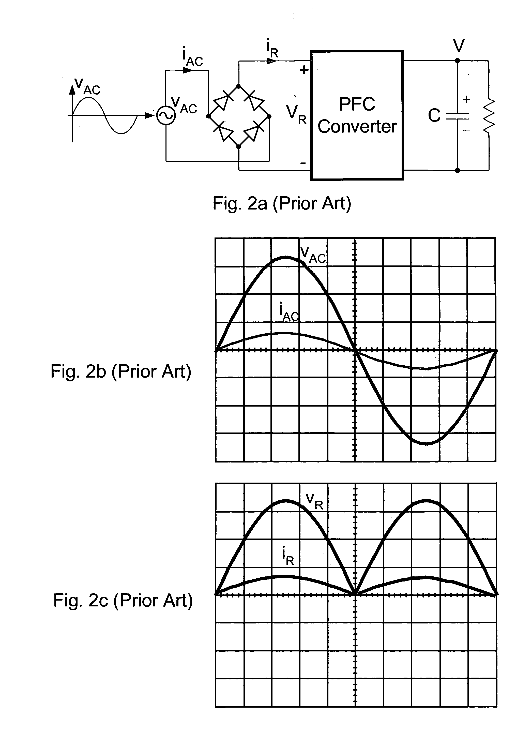
The corresponding two-diode voltage drops for low AC line voltage of 85VAC result in additional 3% losses making a total conversion losses of around 6%.
However, they all failed to achieve the desirable goal of eliminating input bridge as they were all based on the various modifications of the boost converter of FIG. 3a, which can operate only from the positive polarity of the input voltage.
Therefore, in all prior-art configurations of FIG. 5, FIG. 6, FIG. 7, FIG. 8, and FIG. 9, one may discover the additional diode voltage drops in the power paths or extra conduction power loss.
For example, the prior-art converter of FIG. 5 although appearing to have smaller number of semiconductor switches, the two controlling switches S1 and S2 must be for one half of AC cycle ON all the time (not in pulsed mode) thereby both resulting in extra losses.
The prior art-converter of FIG. 6 has additional problem that it is limited to operation in Discontinuous Inductor Current mode.
Additional disadvantage is that all four diodes are high switching frequency diodes and not low AC line 60 Hz frequency rectifiers.
Therefore, in addition to the reduced efficiency due to additional diode voltage drops (only two diodes in the full-bridge are eliminated), it also suffers from doubling the cost in comparison to the previous prior-art implementations.
Thus, the components in double-boost converter of FIG. 8 are poorly utilized, as they are used only half of the time while during the other half time they idle resulting in serious penalty in weight, size and cost.

Method used


Image

  • Bridgeless PFC converter
  • Bridgeless PFC converter
  • Bridgeless PFC converter

Examples


experimental verifications

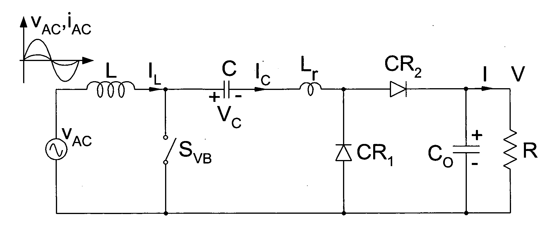
[0059]The Bridgeless PFC converter is verified by on an experimental 400W prototype, which converts 110V AC line voltage into a 400V DC output voltage. FIG. 18a shows the line voltage (top trace) and AC line current (bottom trace). The Power Factor was measured at 300 W load to be 0.997.

[0060]Very high efficiency of over 97% was measured over the wide input AC voltage range. In particular, note the very high efficiency at the low AC line voltage of 85VAC as shown in FIG. 19a while the power losses are shown in FIG. 19b. This clearly indicates the absence of the bridge rectifier on the front. The prior-art PFC converters have a significant efficiency drop at the low 85V AC line due to the two-diode voltage drops. This is clearly one of the key advantages of the new Bridgeless PFC converter.


PUM


Abstract

A truly Bridgeless PFC converter is provided which eliminates the four-diode bridge rectifier and operates directly from the AC line to result in high-efficiency, small size and low cost solution for Power Factor Correction applications.

Description

CROSS-REFERENCE TO RELATED APPLICATIONS[0001]Provisional U.S. Patent Application No. 61 / 212,430[0002]Filed on Apr. 11, 2009[0003]Applicant: Slobodan Cuk[0004]Title: Bridgeless PFC Converter[0005]Confirmation Number: 9358FIELD OF THE INVENTION[0006]This invention relates to the field of switching DC-to-DC converters and more specifically to their use as a Power Factor Correction (PFC) converter part of an AC-DC converter. When suitably controlled PFC converters force the input AC current wave shape to be sinusoidal and in phase, and proportional with input AC voltage thus resulting in desirable low harmonic content and maximum available real power drawn from the AC line.[0007]This invention also relates to the DC-DC converters, which have DC voltage step-up characteristic as this is a desired prerequisite for performing Power Factor Correction function. Prior-art boost converter is the most often used converter for that application. As the front-end diode bridge is inefficient, many ...

Claims


Application Information

Patent Timeline
Patent Type & Authority Applications(United States)
IPC IPC(8): G05F5/00
CPCH02M1/4208H02M1/4258Y02B70/1425Y02B70/126H02M3/005H02M1/0085Y02B70/10
Inventor CUK, SLOBODAN
Owner CUKS
Why Eureka
Try Eureka