
Systems and methods for augmenting diode rectifiers with active compensators

A diode rectifier and compensator technology, applied in reactive power compensation, active power filtering, reactive power adjustment/elimination/compensation, etc., can solve the problem that the generator unit does not work or control with optimal efficiency

Active Publication Date: 2018-04-06
ABB (SCHWEIZ) AG
View PDF5 Cites 0 Cited by
  • Summary
  • Abstract
  • Description
  • Claims
  • Application Information

AI Technical Summary

Problems solved by technology

In addition, generator units providing reactive power are not operating at optimal efficiency or controlled

Method used


Image

  • Systems and methods for augmenting diode rectifiers with active compensators
  • Systems and methods for augmenting diode rectifiers with active compensators
  • Systems and methods for augmenting diode rectifiers with active compensators

Examples


Embodiment Construction

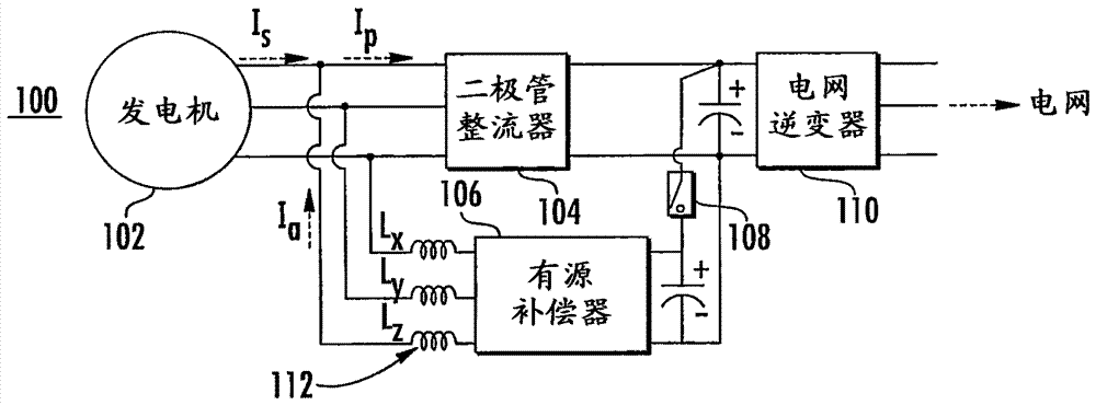
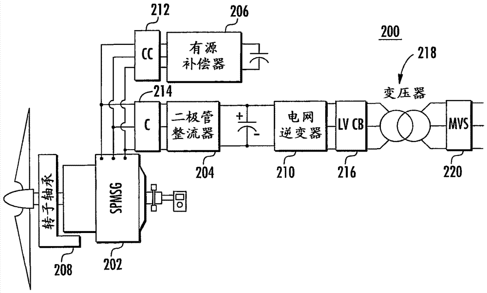
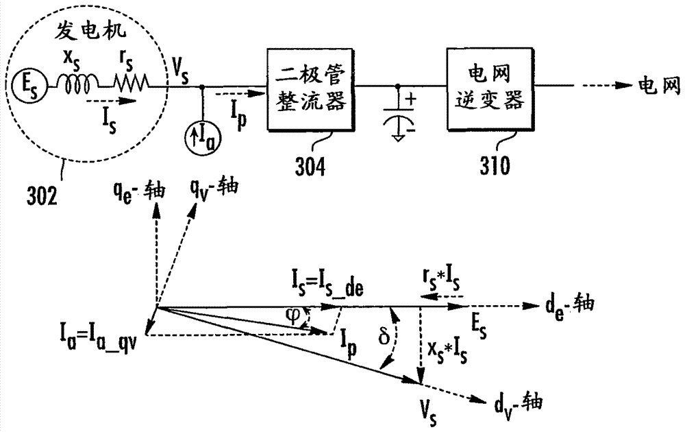
[0013] The present subject matter includes a power generation system (such as a wind power system) utilizing a fully rated diode rectifier and a fractional rated active compensator that reduces the cost of the system and optimizes the performance of the system's generator units. In one embodiment, the generator unit can be optimized by controlling the generator voltage via a control method involving an active compensator by combining the quadrature (q-axis) current and the direct-axis (d-axis) current in a synchronous frame of reference. The current is adjusted to the optimal operating point to inject reactive power into the generation system. The q-axis is usually used to represent reactive (ie, imaginary) power and current components, while the d-axis is usually used to represent active (ie, real) power and current components.

[0014] As used herein, the terms "reactive power" and "reactive current" refer to the power flow and current flow used to facilitate the transfer of...


PUM


Abstract

The subject matter described herein includes an actively compensated augmented diode bridge rectifier system. According to one aspect, the system includes: a generator unit configured to generate a current flow consisting entirely of real current; and a diode rectifier configured to receive the real current from the generator unit to direct the real current to the connected power grid and receives reactive current. The system also includes an active compensator configured to optimize the generator unit to generate real current and generate reactive power to facilitate operation of the diode rectifier.

Description

technical field [0001] The subject matter described herein relates to providing a source of reactive power for an electric machine generator. More specifically, the subject matter described herein relates to systems and methods for augmenting diode rectifiers with active compensators. Background technique [0002] Currently, 100% kilovolt-ampere (kVA) rated power converter wind energy solutions are more prevalent despite the fact that the market is dominated by doubly-fed induction generators (DFIG) utilizing 40% kVA rated (approximate) power converters . In particular, wind power system solutions based on 100% kVA rated power converters can offer attractive features such as improved low voltage ride through (LVRT) capability, better generator utilization, and wider speed range. However, a 100% kVA rated power converter wind energy solution is more expensive, heavier and larger than a 40% kVA rated power converter. To overcome the aforementioned disadvantages, a diode bri...

Claims


Application Information

Patent Timeline
Patent Type & Authority Patents(China)
IPC IPC(8): H02J3/38H02J3/18H02M7/06
CPCH02J3/18H02J3/1842H02M1/12H02P9/007H02P23/26H02M1/4283Y02B70/10Y02E10/76Y02E40/20Y02E40/30
Inventor 金弘来J·尼拉南J·J·萨斯特里
Owner ABB (SCHWEIZ) AG
Learn More