Injection locked phase lock loops

a phase lock and lock loop technology, applied in the direction of electrical equipment, pulse automatic control, etc., can solve the problems of unsatisfactory phase noise and the increase in the overall noise of the pll circuit with the increase in the amount of phase nois

Inactive Publication Date: 2010-10-14
NAT TAIWAN UNIV
View PDF10 Cites 28 Cited by
  • Summary
  • Abstract
  • Description
  • Claims
  • Application Information

AI Technical Summary

Benefits of technology

[0007]Signal generating circuits are provided. An exemplary embodiment of a signal generating circuit for generating an output signal comprises a phase detection circuit and an injected controlled oscillator. The phase detection circuit is arranged to detect a phase difference between an input reference signal and a feedback signal and generate a control signal according to the phas...

Problems solved by technology

However, inherent inaccurate oscillation causes the oscillator frequency to drift around the target frequency, introducing undesired phase noise. FIG....

Method used


Image

  • Injection locked phase lock loops
  • Injection locked phase lock loops
  • Injection locked phase lock loops

Examples


Embodiment Construction

[0023]The following description is of the best-contemplated mode of carrying out the invention. This description is made for the purpose of illustrating the general principles of the invention and should not be taken in a limiting sense. The scope of the invention is best determined by reference to the appended claims.

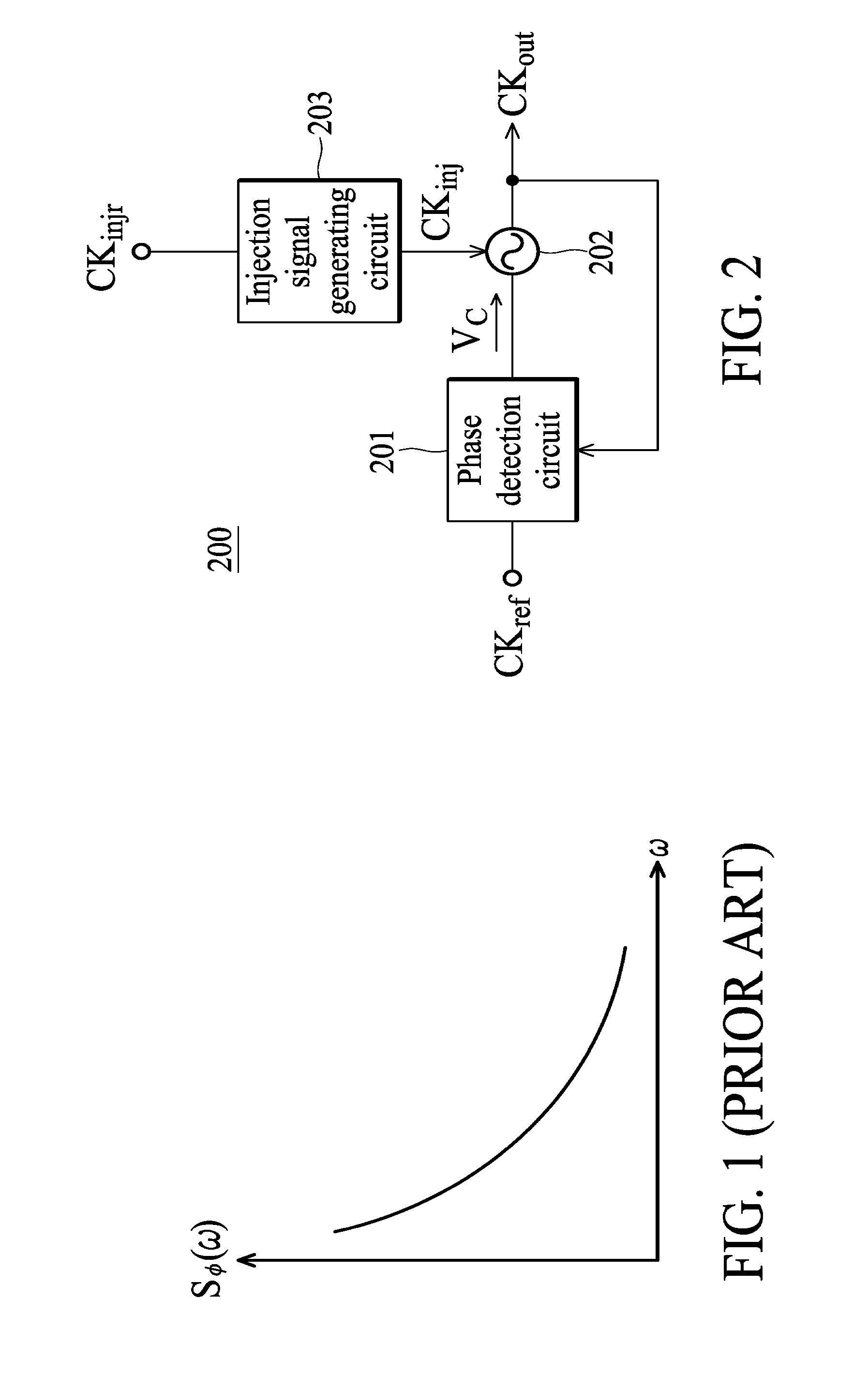
[0024]FIG. 2 shows a block diagram of a signal generating circuit according to an embodiment of the invention. The signal generating circuit 200 generates an output signal CKout according to an input reference signal CKref. A frequency of the output signal CKout is proportional to a frequency of the input reference signal CKref. As an example, the frequency of the output signal CKout may be a multiple of that of the input reference signal CKref, so as to generate an output signal with multiple times the frequency of the input reference signal CKref. As shown in FIG. 2, the signal generating circuit 200 comprises a phase detection circuit 201, an oscillator 202 and an i...


PUM


Abstract

A signal generating circuit for generating an output signal is provided. A phase detection circuit is arranged to detect a phase difference between an input reference signal and a feedback signal, and generate a control signal according to the phase difference. An injected controlled oscillator is arranged to receive the control signal and an injection signal and generate the output signal according to the control signal and the injection signal. A frequency of the output signal is proportional to a frequency of the input reference signal, and a frequency of the injection signal does not equal to the frequency of the output signal.

Description

CROSS REFERENCE TO RELATED APPLICATIONS[0001]This application claims priority of Taiwan Patent Application No. 098111632, filed on Apr. 8, 2009, the entirety of which is incorporated by reference herein.BACKGROUND OF THE INVENTION[0002]1. Field of the Invention[0003]The invention relates to an injection locked Phase Lock Loop (PLL), and more particularly to a sub-harmonic injection locked PLL.[0004]2. Description of the Related Art[0005]Phase Lock Loop (PLL) is basically a closed loop frequency control system, wherein operation is based on the phase sensitive detection of the phase differences between a feedback signal and a reference signal. A PLL circuit usually includes a controlled oscillator, a divider, a frequency phase detector (PFD), a charge pump, and a loop filter. The PLL circuit responds to both the frequency and the phase of input signals, automatically raising or lowering the frequency of the controlled oscillator until a feedback signal is matched to a reference signa...

Claims


Application Information

Patent Timeline
IPC IPC(8): H03L7/08
CPCH03L7/099H03L2207/06H03L7/24H03L7/23
Inventor LEE, JRIWANG, HUAI-DE
Owner NAT TAIWAN UNIV
Why Eureka
Try Eureka