High-precision fiber frequency transmission system

A technology of optical fiber frequency and transmission system, applied in the direction of optical fiber transmission, transmission system, electromagnetic wave transmission system, etc., can solve the problems of limiting system accuracy, fiber ring polarization-related loss, system complexity increase, etc., and achieve high bandwidth response and large dynamic range, the effect of increasing system stability and applicability

Active Publication Date: 2017-06-20
SHANGHAI INST OF OPTICS & FINE MECHANICS CHINESE ACAD OF SCI
View PDF5 Cites 29 Cited by
  • Summary
  • Abstract
  • Description
  • Claims
  • Application Information

AI Technical Summary

Problems solved by technology

However, it is difficult for the optical fiber delay line used in this method to simultaneously achieve high bandwidth response and large dynamic range. The cascading of two fiber delay lines with dynamic range and low bandwidth response (temperature control) characteristics will also lead to an increase in system complexity, and the piezoelectric ceramic and temperature-controlled fiber rings are very easy to cause polarization-dependent losses, etc. Some other problems limit the further improvement of system accuracy

Method used


Image

  • High-precision fiber frequency transmission system
  • High-precision fiber frequency transmission system
  • High-precision fiber frequency transmission system

Examples


specific Embodiment

[0018] The specific embodiment of the high-precision optical fiber frequency transmission system of the present invention is as follows:

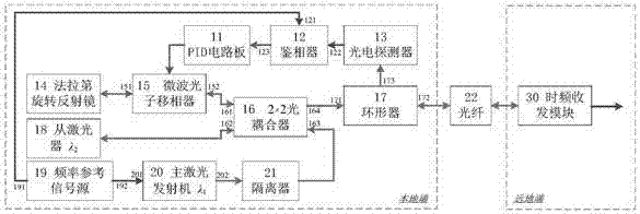
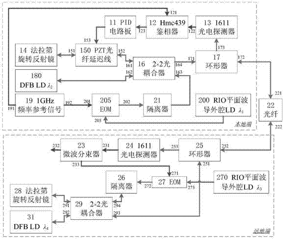
[0019] This example figure 2shown. The electro-optical modulator EOM 205 and the RIO planar waveguide external cavity LD 200 constitute the main laser transmitter 20, the first port 191 of the frequency reference signal source 19 at the local end is connected to the first input port 121 of the hmc439 phase detector 12, and the frequency reference signal source The second port 192 of 19 is connected with the microwave signal input port 201 of the electro-optical modulator EOM 205, and the optical input port 203 of the EOM 205 is connected with the RIO planar waveguide external cavity LD 200, and the optical output port 202 of the EOM 205 is connected with the isolator 21 The input port is connected, the output port of the isolator 21 is connected with the third port 163 of the 2×2 optical coupler 16, and the first port 161 of the 2×2 optic...


PUM


Abstract

The invention discloses a high-precision fiber frequency transmission system, and the system comprises a PID circuit board, a phase discriminator, a photoelectric detector, a Faraday rotary reflector, a microwave photon phase shifter, a 2*2 optical coupler, a circulator, a slave laser, a frequency reference signal source, a main laser emitter, an isolator, an optical fiber link, and a time frequency receiving and transmitting module. On the basis of a single-fiber bidirectional return error signal obtaining mode, the system carries out the optical fiber link noise compensation based on injection locked coherent detection and the microwave photon phase shifter, thereby achieving the high-precision fiber frequency transmission. The system can achieve the high-precision recovery of a frequency reference signal of a local end at a far end. The system can achieve the two features, needed by phase change, on the same microwave photon phase shifter at the same time: large-bandwidth response and large dynamic range, facilitates the reduction of the complexity, and improves the stability and adaptability. The system can be used in the fields of comparison of the optical clock/atomic clock and the frequency transmission.

Description

technical field [0001] The present invention relates to high-precision frequency transmission, especially a high-precision optical fiber frequency transmission system, the main purpose of which is to compensate the link noise of frequency transmission in the optical fiber, so as to recover the frequency reference signal of the local end at the remote end with high precision, which can It is used in clock comparison, frequency transmission and other fields such as optical clock / atomic clock. Background technique [0002] Frequency standards are the basis of various important technologies in modern society, such as navigation and positioning, interconnection and communication, and accurate testing of physical constants. With the successful development of high-precision clocks such as hydrogen clocks, cold atomic clocks, fountain clocks, and optical clocks, the frequency standard accuracy is getting higher and higher, and the technology is becoming more and more mature. For exa...

Claims


Application Information

Patent Timeline
Patent Type & Authority Applications(China)
IPC IPC(8): H04B10/25H04B10/548
CPCH04B10/25891H04B10/548
Inventor 杨飞冯子桐张茜蔡海文桂有珍程楠魏芳
Owner SHANGHAI INST OF OPTICS & FINE MECHANICS CHINESE ACAD OF SCI
Why Eureka
Try Eureka