Current reused stacked ring oscillator and injection locked divider, injection locked multiplier

a technology of stacked ring oscillators and multipliers, which is applied in the direction of pulse techniques, continuously circulated pulse counters, count chain synchronous pulse counters, etc., can solve the problems that the power consumed by the frequency divider is a substantial portion of the total power consumption of the phase locked loop, and the standard frequency divider consumes large amounts of power, so as to reduce the power consumption

Active Publication Date: 2015-04-28
STMICROELECTRONICS INT NV
View PDF7 Cites 27 Cited by
  • Summary
  • Abstract
  • Description
  • Claims
  • Application Information

AI Technical Summary

Benefits of technology

[0008]One embodiment is a phase locked loop including a voltage controlled oscillator and a frequency divider having reduced power consumption. The voltage controlled oscillator is driven by a fixed drive current provided

Problems solved by technology

However, standard frequency dividers consume large amounts of power.
In particular, at RF frequencies the powe

Method used


Image

  • Current reused stacked ring oscillator and injection locked divider, injection locked multiplier
  • Current reused stacked ring oscillator and injection locked divider, injection locked multiplier
  • Current reused stacked ring oscillator and injection locked divider, injection locked multiplier

Examples


Embodiment Construction

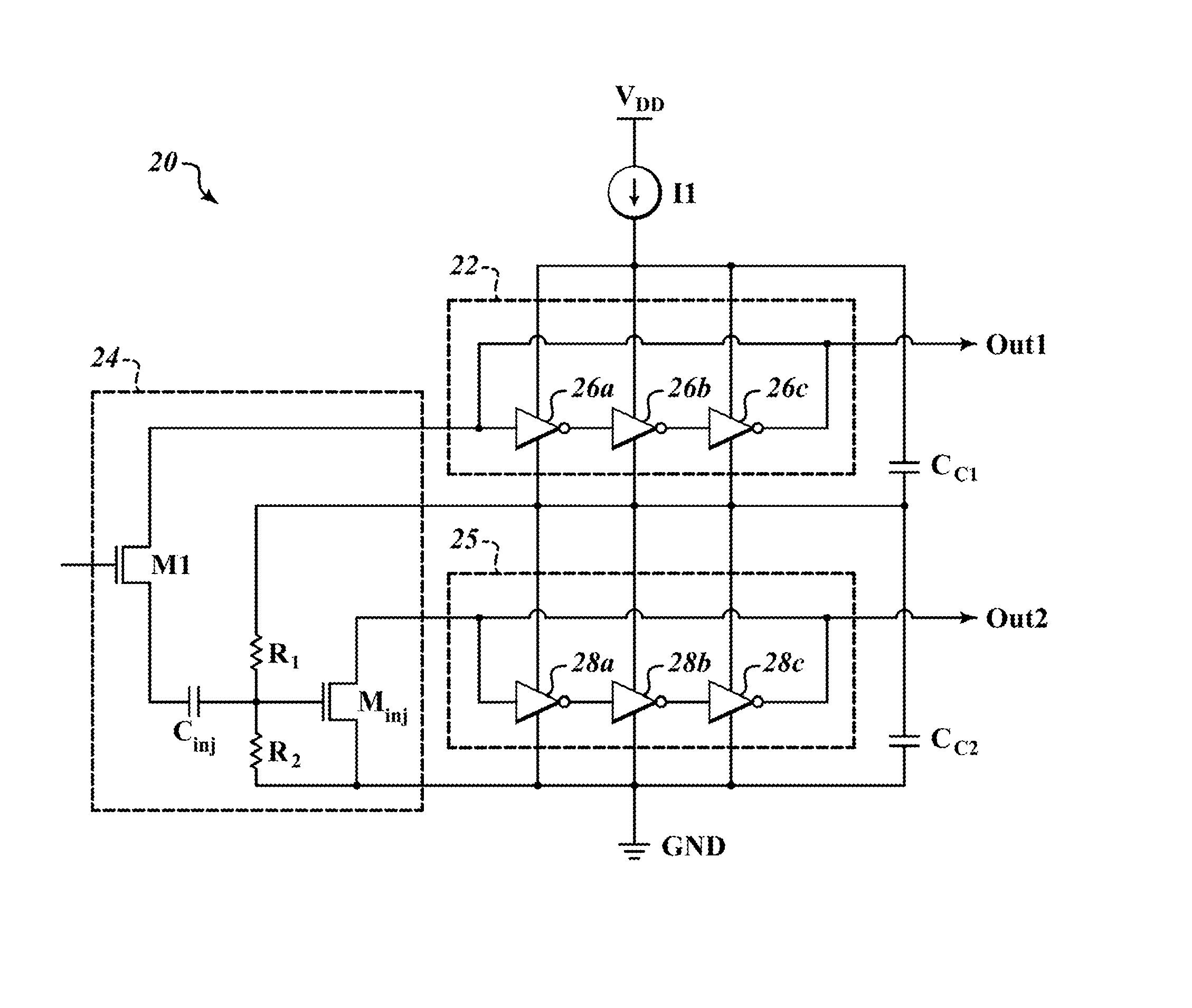
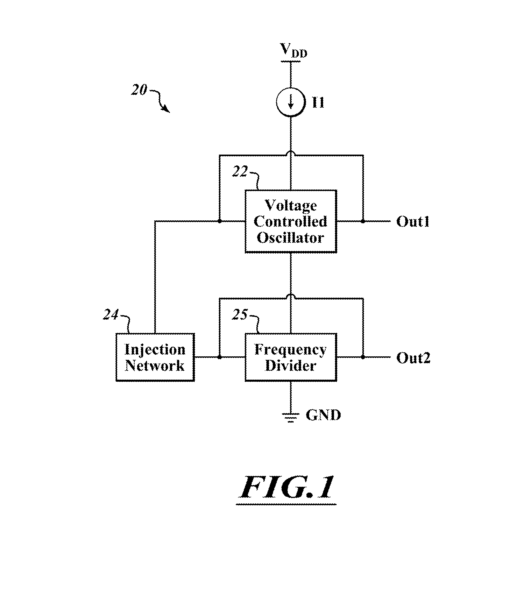
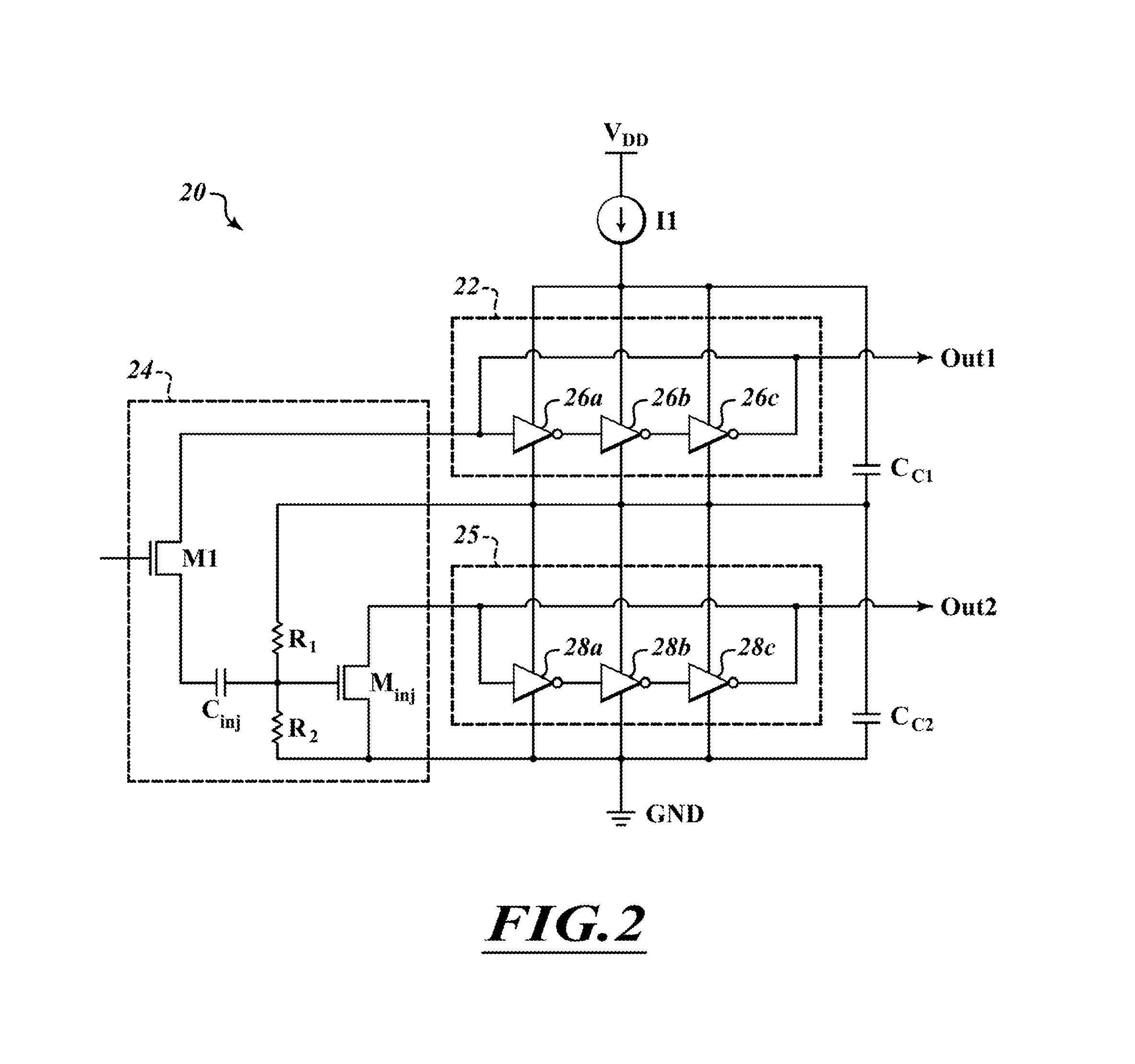
[0019]FIG. 1 is a block diagram of a portion of a phase locked loop 20 according to one embodiment. The phase locked loop 20 includes a voltage controlled oscillator 22, an injection network 24, and a frequency divider 25. A current source I1 supplies a drive current to the voltage controlled oscillator 22.

[0020]The voltage controlled oscillator 22 generates an oscillation signal OUT1. The oscillation signal OUT1 has a particular frequency according to the structure of the voltage controlled oscillator, the driving current, and an input frequency signal (not shown). The oscillator signal is supplied to the input of the voltage controlled oscillator 22.

[0021]The injection network 24 receives the oscillation signal from the voltage controlled oscillator 22. The injection network 24 removes the DC component of the output oscillation signal and provides the oscillating component to the frequency divider 25.

[0022]The frequency divider receives an injection oscillation signal from the inj...


PUM


Abstract

A phase locked loop includes a voltage controlled oscillator and a frequency divider or frequency multiplier. The voltage controlled oscillator and the frequency divider/multiplier are coupled together in a stacked configuration. A drive current is supplied to the voltage controlled oscillator. The drive current passes from the voltage controlled oscillator to the frequency divider/multiplier, thereby driving the frequency divider/multiplier with the same drive current that was supplied to the voltage controlled oscillator.

Description

BACKGROUND[0001]1. Technical Field[0002]The present disclosure relates to the field of voltage controlled oscillators. The present disclosure relates more particularly to the field of ring oscillators.[0003]2. Description of the Related Art[0004]Phase locked loops are commonly used in integrated circuits to ensure that clock signals used throughout the integrated circuit die have phases that are locked together. Phase locked loops typically include a voltage controlled oscillator (VCO) that generates an oscillator signal having a particular frequency. Typically, the phase locked loop also includes an input oscillator signal. The phase locked loop ensures that the phase of the input oscillator signal and the phase of the oscillator signal generated by the VCO are locked together in a particular relationship.[0005]To assist in this, the phase locked loop typically includes a frequency divider that divides the oscillator signal by some integer number. The frequency divider is in the fe...

Claims


Application Information

Patent Timeline
IPC IPC(8): H03B19/00H03K3/03H03K23/54H03L7/00H03L7/099
CPCH03L7/00H03K3/0315H03K23/54H03L7/0995H03L7/24
Inventor LAHIRI, ABHIRUP
Owner STMICROELECTRONICS INT NV
Why Eureka
Try Eureka