
Follow Focus Camera Accessory Device

a technology of accessory devices and cameras, which is applied in the field of follow focus devices, can solve the problems of difficult to use the follow focus devices in a variety of applications, and achieve the effect of preventing errors resulting from improper placement of annular indexing members and facilitating releasability structur

Inactive Publication Date: 2010-10-14
WOOD DENNIS
View PDF3 Cites 42 Cited by
  • Summary
  • Abstract
  • Description
  • Claims
  • Application Information

AI Technical Summary

Benefits of technology

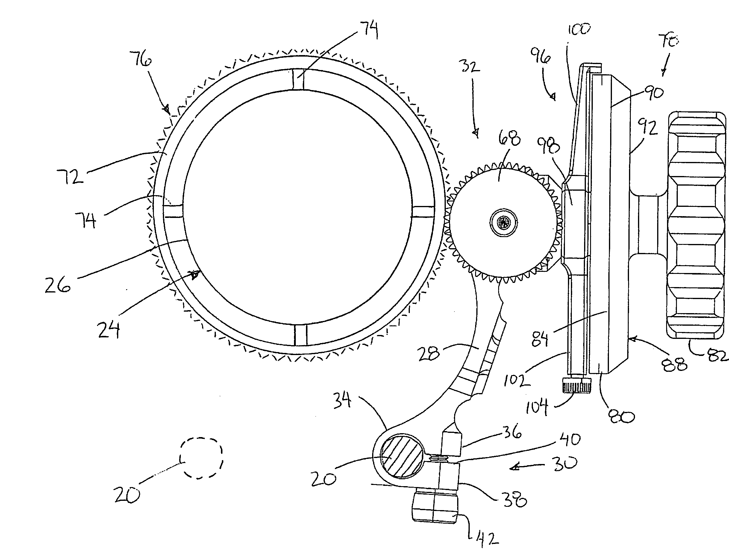
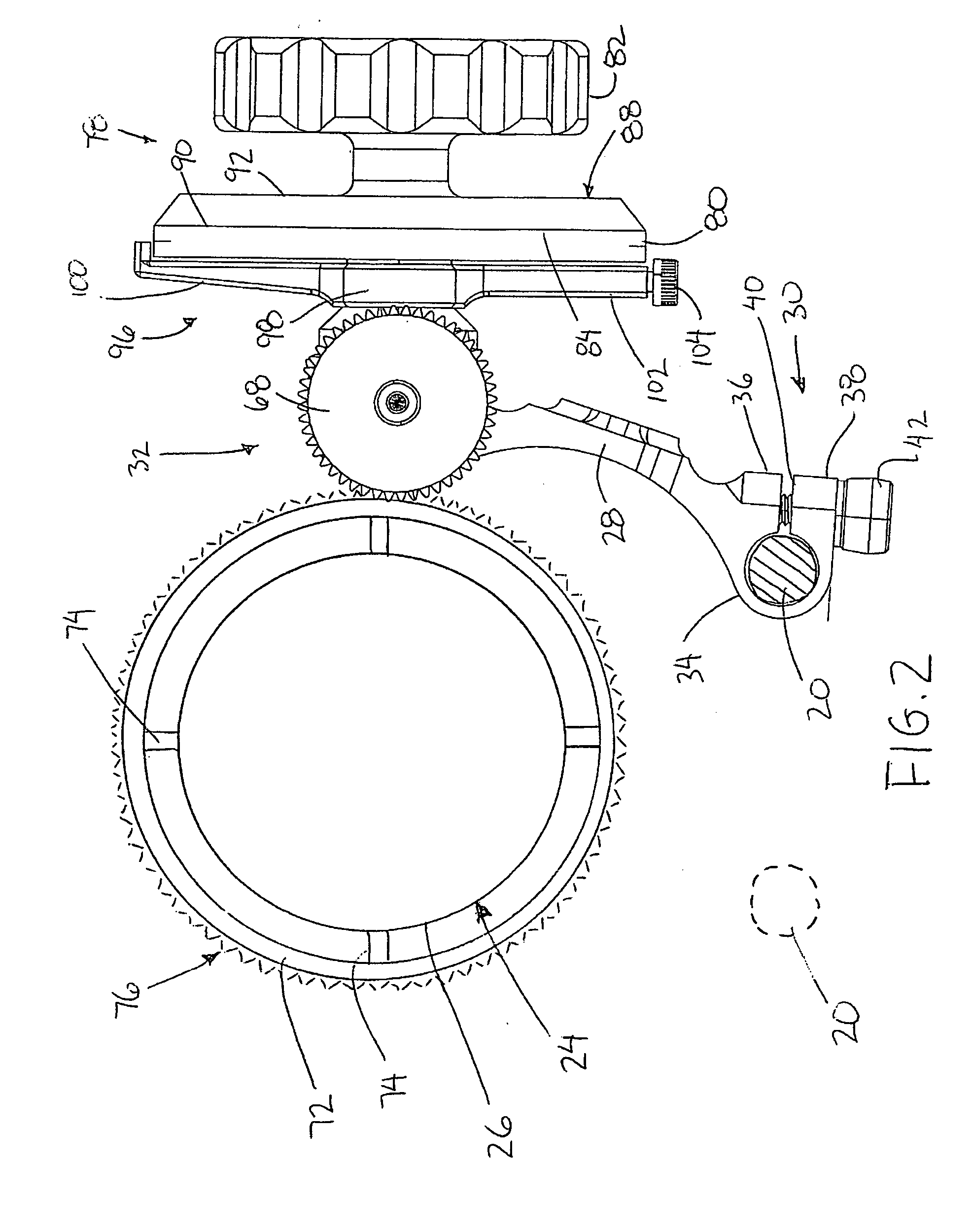
[0013]By providing a mount which is permitted to pivot about a single mounting rail, a follow focus device is provided which can be mounted in an unlimited amount of configurations as the device can readily be reversed along the mounting rail or slidably displaced along the rail while optionally being mounted on a different one of the two mounting rails of a camera assembly. In yet further arrangements the single rail mounting configuration is also convenient for supporting the follow focus accessory device on an auxiliary mounting rail supported on a cage for example. The configuration of the input to the output of the transmission is thus reversible along the same rail for changing the direction of the output relative to the input as well as being reversible to the other rail for similarly changing the direction of rotation on either side of the camera lens. Due to the pivoting arrangement of the main body relative to the mounting rail location of the output can be readily adjusted for engaging a focusing ring on the lens without any complex placement of slides or transmission reconfigurations being required as in the prior art devices.
[0031]By further providing a transmission which can be readily mounted in two reversible orientations between spaced apart mounting portions of the main body, the direction of rotation of the output relative to the input can be further adjusted without altering the orientation of the main body relative to the mounting rail. Providing a transmission which is readily reversible as an integral unit provides a simple reconfigurable structure which is highly adaptable to various configurations and different applications or desired uses of the focusing accessory device.
[0043]Use of an index marker which is rotatable about the control axis independently of the indexing member further increases the flexibility of mounting configurations as the index marker relative to which the annular indexing member is rotated can be located to best suit the orientation of the control knob and main body relative to the mounting rail upon which it is supported. The increased customization by the user which is permitted ensures that the focusing accessory device is more adaptable to different applications than prior art devices intended for similar use.
[0057]By ensuring the annular indexing member can only be mounted in a single orientation relative to the control knob, errors resulting from improper placement of the annular indexing member are prevented. In this manner the convenience of having a quick and readily releasable structure which can be replaced for different indexing scenarios can be realised without introducing any further complications of misalignment of the annular indexing member with its intended mounting orientation.

Problems solved by technology

In each instance in the prior art due to the mounting configuration on two spaced apart mounting rails of the camera assembly, and due to the limited adjustment ability of the control knob and output relative to the rail mounts, very few mounting orientations are permitted so that it is difficult to make use of the follow focus device in a variety of applications.

Method used


Image

  • Follow Focus Camera Accessory Device
  • Follow Focus Camera Accessory Device
  • Follow Focus Camera Accessory Device

Examples


Embodiment Construction

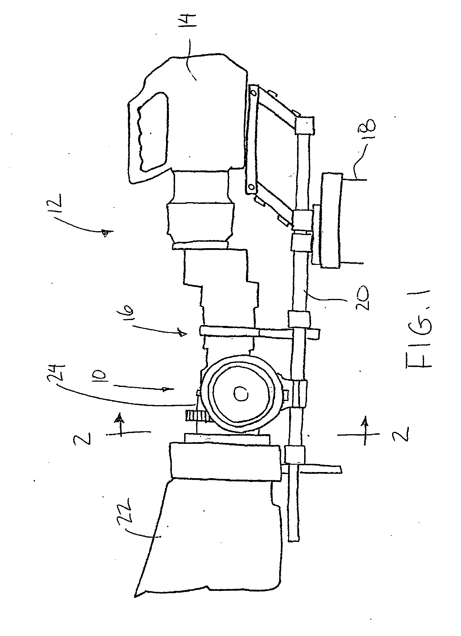
[0069]Referring to the accompanying figures there is illustrated a camera focusing accessory device generally indicated by reference numeral 10. The device 10 is suited for use with a video camera assembly 12 of the type shown in FIG. 1.

[0070]The video camera assembly 12 typically comprises a camera body 14 which is directed in a longitudinal direction for capturing images through a lens assembly 16 coupled to the camera body. The camera assembly is commonly supported on a supporting structure such as a tripod 18 by a pair of mounting rails 20 which extend in the longitudinal direction parallel and spaced apart from one another. The mounting rails are typically fixed to the top of the tripod 18 and the camera body 14 and lens assembly 16 are then supported on the mounting rails using suitable mounting hardware. Additional components of the camera assembly, for example a matte box 22 can also be supported on the mounting rails. Each of the mounting rails in the illustrated embodiment...


PUM


Abstract

A focussing accessory device comprises a focussing ring rotatable with a focussing control of a video camera rotatable responsive to rotation of a control knob. A main body of the device is supported on a single mounting rail of a camera assembly for relative pivotal movement to adjust an orientation of the device relative to the camera. The control knob is coupled to an input of a transmission on the main body. An output of the transmission meshes in engagement with the focussing ring. The transmission is reversibly supported on the main body to reverse the location and orientation of the output. An index marker is provided for rotation about an axis of the control knob independently therefrom. An annular indexing member is selectively coupled for rotation with the control knob relative to the index marker by magnetic elements which permit mounting in only one relative orientation.

Description

FIELD OF THE INVENTION[0001]The present invention relates to a focussing accessory device for a camera, and more particularly relates to a follow focus device to provide auxiliary control of the manual focus of a lens of a video camera.BACKGROUND[0002]It is common in the use of video cameras to additionally make use of a follow focus accessory device. The follow focus device generally comprises a rotatable control knob which rotates relative to an index marker and which in turn rotates an output member that meshes with a corresponding focusing ring supported about the lens of the camera for rotation with a rotating component of the lens used for focusing.[0003]Examples of follow focus devices are available by Zacuto and Chrosziel. In each instance a base is provided which requires anchoring to two spaced apart mounting rails of a camera mounting assembly in order to provide proper support to the device. In some examples a complex arrangement of parts is required to permit relative s...

Claims


Application Information

Patent Timeline
IPC IPC(8): G03B13/18
CPCG03B13/32G03B17/568G03B17/56
Inventor WOOD, DENNIS
Owner WOOD DENNIS
Learn More